Electrical | 13LM Series Heat Pump
8 733 905 315 (2013/9)Revised 09-13
ECM INTERFACE BOARD- Constant
Airflow Motor (Option)
Refer to Figure #9, item [12] for ECM interface
board location. In addition to providing a
connecting point for thermostat wiring, the
interface board also translates thermostat inputs
into control commands for the Electronic
Commutated Motor (ECM) DC fan motor and
provides thermostat signlas to unit’s UPM board.
The thermostat connections and their functions
are as follows:
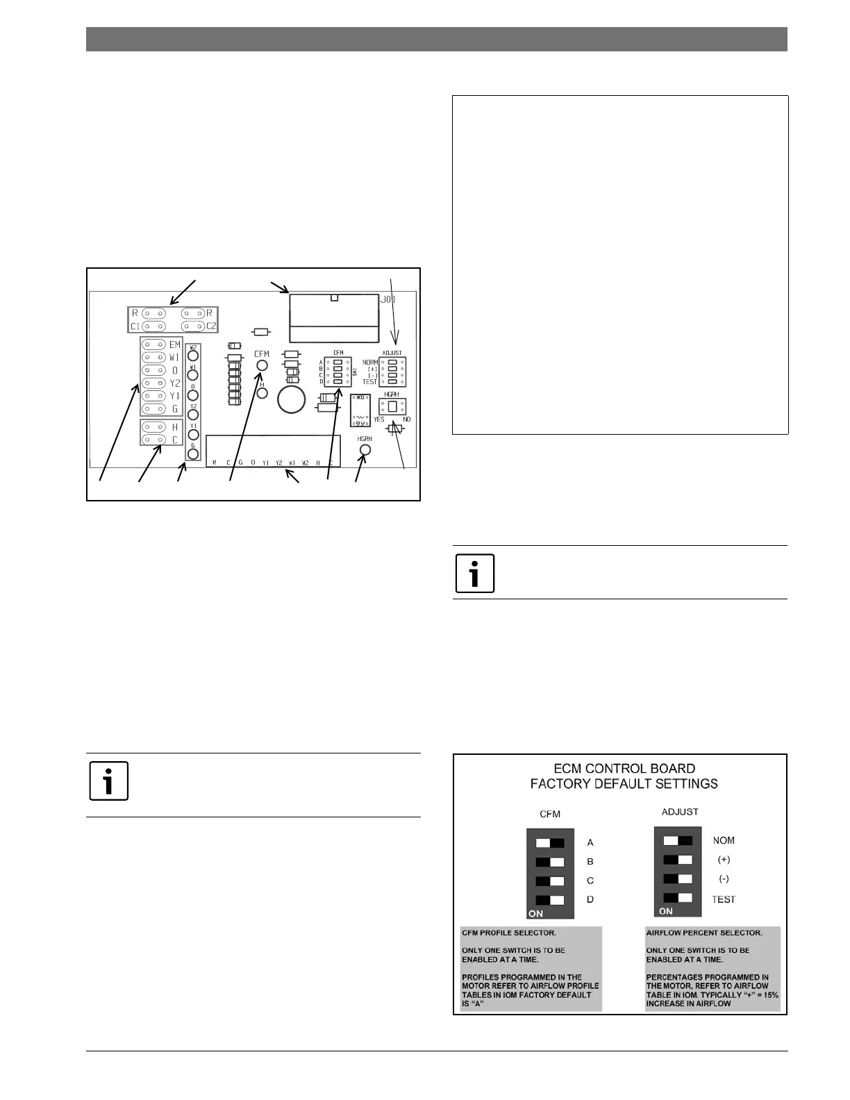
Figure # 13
[1] Motor harness plug
[2] Blower CFM adjustment
[3] Motor settings
[4] Dehumidification indication
[5] Thermostat digital contact inputs
[6] CFM count indicator
[7] Thermostat input status indication
[8] Reheat digital outputs
[9] Thermostat outputs
[10] 24 VAC
[11] Dehumidification method selector
• CFM count indicator (See Figure #13, item [6])
blinks to indicate approximate airflow in CFM
and may flicker when unit is off.
• Each blink of the LED represent approximately
100 CFM of air delivery so if the LED blinks 12
times, pauses, blinks 12 times, etc. the blower
is delivering approximately 1200 CFM.
Airflow Selector
The airflow selector (Figure #13, items [2] & [3])
allows airflow adjustment to meet application
requirements and to ease troubleshooting.
• CFM Selector (FIg #13, Item [2]) must remain
with only “A” being enabled.
• ADJUST Selector can be adjusted to NOM, (+),
(-), or TEST. NOM, (+) and (-) can be adjusted
as needed by application. TEST is used for
troubleshooting to override unit airflow to
100%.
CFM LED indication is an approximation. Utilize
conventional Test and Balance equipment for
accurate airflow measurement.
Thermostat Outputs
Y1 First Stage Compressor Operation
Y2 Second Stage Compressor Operation
GFan
O Reversing Valve (energized in cooling)
W1 Auxiliary Electric Heat (runs in conjunction
with compressor)
EM/W2 Emergency Heat (electric heat only)
NC Transformer 24 VAC Common (extra
connection)
C1 Transformer 24 VAC Common (primary
connection)
R Transformer 24 VAC Hot
H Dehumidification Mode
Only one switch can be enabled at a time. Refer
to Figure #22 for each airflow setting.
 Loading...