20 | English
1 619 929 J54 | (24.10.11) Bosch Power Tools
another. It may be used for a preliminary assessment of expo-
sure.
The declared vibration emission level represents the main ap-
plications of the tool. However if the tool is used for different
applications, with different accessories or poorly maintained,
the vibration emission may differ. This may significantly in-
crease the exposure level over the total working period.
An estimation of the level of exposure to vibration should also
take into account the times when the tool is switched off or
when it is running but not actually doing the job. This may sig-
nificantly reduce the exposure level over the total working pe-
riod.
Identify additional safety measures to protect the operator
from the effects of vibration such as: maintain the tool and the
accessories, keep the hands warm, organisation of work pat-
terns.
Technical Data
Declaration of Conformity
We declare under our sole responsibility that the product de-
scribed under “Technical Data” is in conformity with the fol-
lowing standards or standardization documents: EN 61029,
EN 60825-1 according to the provisions of the directives
2011/65/EU, 2004/108/EC, 2006/42/EC.
Technical file (2006/42/EC) at:
Robert Bosch GmbH, PT/ETM9,
D-70745 Leinfelden-Echterdingen
Robert Bosch GmbH, Power Tools Division
D-70745 Leinfelden-Echterdingen
Leinfelden, 24.10.2011
Assembly
f Avoid unintentional starting of the machine. During as-
sembly and for all work on the machine, the power plug
must not be connected to the mains supply.
Delivery Scope
Before starting the operation of the machine for the first time,
check if all parts listed below have been supplied:
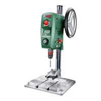
– Motor unit 12 with drilling column 4
– Base plate 1
– Quick-clamping device 3
– Parallel guide 19
– Allen key 23
Note: Check the power tool for possible damage.
Before further use of the machine, check that all protective
devices are fully functional. Any lightly damaged parts must
be carefully checked to ensure flawless operation of the tool.
All parts must be properly mounted and all conditions fulfilled
that ensure faultless operation.
Damaged protective devices and parts must be immediately
replaced by an authorised service centre.
Mounting Individual Components (see figure A)
Before putting into operation for the first time, the machine
must be assembled as follows:
– Slide the quick-clamping device 3 over the drilling column
4.
– Insert the drilling column 4 into the base plate 1 in such a
manner that the guide cog 25 engages in the guide groove
26.
– Firmly tighten fastening screw 24 with Allen key 23.
Mounting to a Working Surface (see figure B)
f To ensure safe handling, the machine must be mounted
on a level and stable surface (e. g., workbench) prior to
using.
– Fasten the power tool with suitable screw fasteners to the
working surface. The mounting holes 18 serve for this
purpose.
Drill Press PBD 40
Article number
3 603 M07 0..
Rated power input
W 710
No-load speed
–1st gear
– 2nd gear
min
-1
min
-1
200–850
600–2500
Laser type
nm
mW
650
<1
Laser class
2
Max. drilling dia.
–Steel
– Wood
mm
mm
13
40
Chuck clamping range
mm 1.5–13
Drill stroke, max.
mm 90
Total height
mm 650
Size of base plate
(Width x depth x height)
mm 330 x 350 x 30
Weight according to
EPTA-Procedure 01/2003
kg 11.2
Protection class
/II
The values given are valid for a nominal voltage [U] of 230 V. For differ-
ent voltages and models for specific countries, these values can vary.
Please observe the article number on the type plate of your machine.
The trade names of the individual machines may vary.
Dr. Egbert Schneider
Senior Vice President
Engineering
Dr. Eckerhard Strötgen
Engineering Director
PT/ESI
OBJ_BUCH-1183-004.book Page 20 Monday, October 24, 2011 11:35 AM
 Loading...