Installation instructions
Tronic 1000 – 6720876020 (2021/05)
20
3 Installation instructions
Install the continuous-flow heater as described in the
illustrated section. Observe the instructions in the text.
3.1 Installation
I. Unpacking/scope of supply
• Unpack the appliance and check for transport damage.
• Dispose of the packaging and, where applicable, the old
appliance, in an environmentally conscious manner.
3.1.1 Preparation for installation
CAUTION
Important!
Only use the enclosed installation set.
• Shut off water supply. The electrical connection
(connection cable) must be disconnected from the power
supply. Unscrew the fuse or switch off the circuit breaker.
• There must be a clearance of approximately 60mm on all
sides of the appliance for installation.
• Observe the technical data for the appliance.
• TR1000 5 T, TR1000 6 T, TR1000 6 B: Unscrew
the screws on the housing cover and remove the lid.
II. Wall mounting
• Secure the appliance using the installation template,
screws and wall plugs so that it is vertical and flush against
the wall:
• TR1000 5 T, TR1000 6 T, TR1000 6 B: For an exposed
electrical connection, the different methods of routing the
supply line found on the assembly template must be
observed.
• TR1000 5 T, TR1000 6 T, TR1000 6 B: The sleeve must fit
tightly round the connection cable. If the sleeve is damaged
during installation, the holes must be sealed water-tight.
III. Water connection
A Pressurised connection
• For a pressurized connection, the tap and outlet fittings
must be approved for operation with closed (pressurized)
continuous-flow heater system.
B Depressurised connection
• Fit the jet regulator supplied.
• Check the inserted filter and sleeve in the water inlet.
• Ensure that the connection pipes are fitted to the adapter
along the axis of the pipes.
• Tighten the union nuts firmly to the adapter with an open-
jawed spanner.
The T-piece and flexible connecting hose (for pressurised
connection) are available from a specialist store.
For a depressurised connection, a depressurised fitting must
be used, e.g. fitting BZ13051 which can be obtained as
a special accessory.
IV. Electrical connection
C Flow switch
D Temperature limiter
• TR1000 4 T, TR1000R 4 T: Connect the appliance to the
mains.
TR1000 5 T, TR1000 6 T, TR1000 6 B
The installation of non plug-in ready appliances must be
undertaken by the respective utility operator or by a qualified
specialist company, who can also assist you when you are
requesting the approval of the utility company for installation
of the appliance.
The appliances must be connected with a NYM-J3x4 (mm
2
)
mains lead. Leads with a larger cross-section must not be used.
• Connect the appliance in accordance with the connection
diagram on the strip terminal.
• Screw the housing cover back on.
• After installation, give the user the operating
instructions and explain how the appliance works.
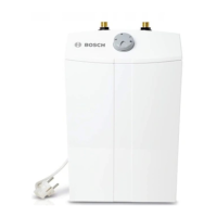
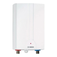
TR1000 6 B High level appliance
TR1000 4 T
TR1000R 4 T
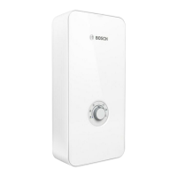
TR1000 5 T
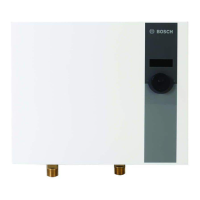
TR1000 6 T
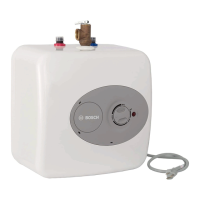
Under counter appliances
1 Housing
2 Mounting (2 screws, 2 wall plugs)
3 ON indicator (only on the TR1000 6 B)
4 Filter and sleeve (inserted in inlet)
5 Jet regulator and seal
6 Only for appliances with a permanent electrical
connection: Rubber grommet
1 Locate the appliance on the screw and press down.
2 Screw in the second screw through the mounting
tab and tighten.
 Loading...