Gas adjustment
63
Greenstar – 6721822579 (2021/01)
▶Measure the CO
2
or O
2
level and the CO content of the flue gas
( Section 13).
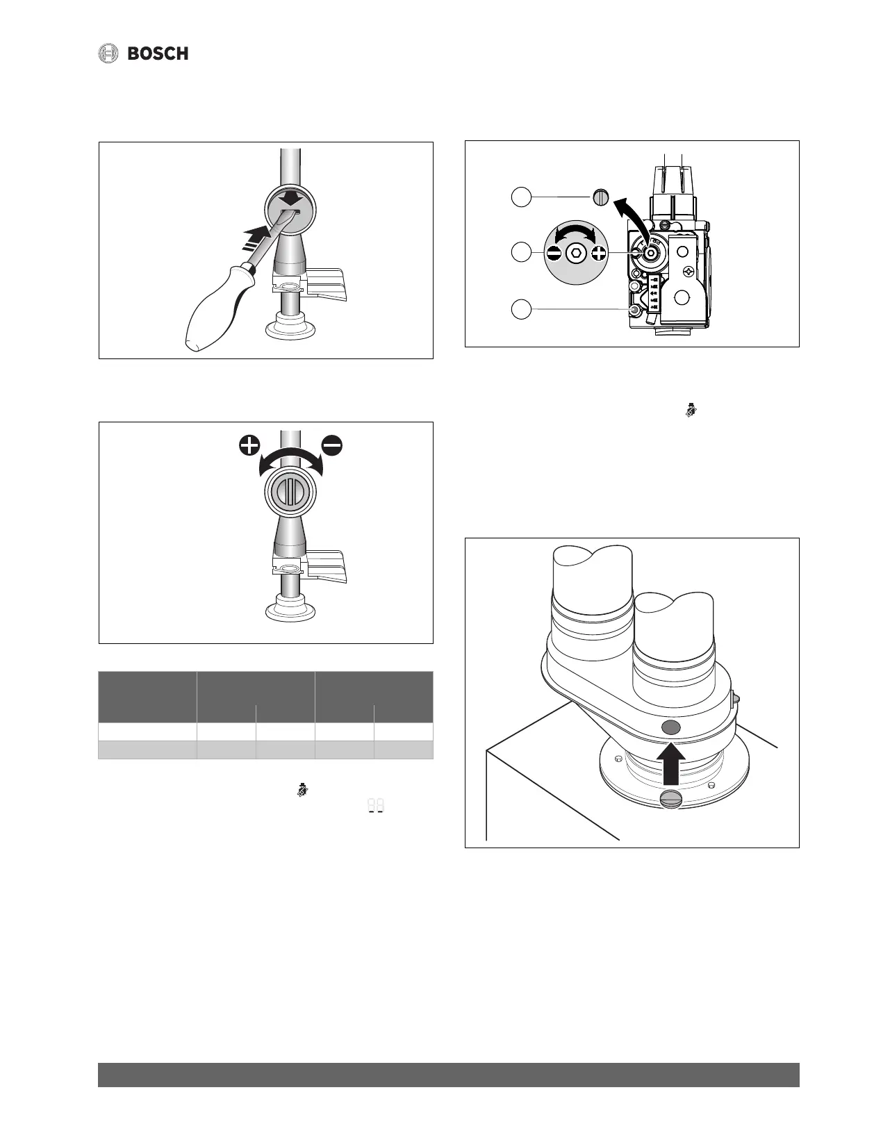
▶ On the gas throttle, break the seal at the slot and remove the cap.
Fig. 77 Remove seal from the gas throttle
▶ Adjust the gas throttle to set the CO
2
or O
2
level for maximum
nominal output according to the table 29.
Fig. 78 Set CO
2
or O
2
level for maximum nominal output
Table 29 CO
2
or O
2
values at maximum and minimum nominal output
▶ Briefly press the emissions test button .
The supply temperature alternates on the display with =
minimum nominal output.
▶Measure the CO
2
or O
2
level and the CO content of the flue gas
( Section 13).
▶ Remove screw ( Fig. 79, [3]) from the gas valve adjustment screw
( Fig. 79, [2]) and set CO
2
or O
2
value for minimum nominal
output.
Fig. 79 Setting the CO
2
or O
2
values for minimum nominal output
▶ Re-check settings at maximum and minimum nominal output and re-
adjust if necessary.
▶ Repeatedly press the emissions test button until the light goes
out.
The display returns to the supply temperature.
▶ Record the CO
2
or O
2
levels and the CO content of the flue gas in the
commissioning log.
▶ Reinstall screw ( Fig. 79, [3]) to cover the adjustment screw
( Fig. 79, [2]) on the gas valve again.
▶ Remove flue gas probe and close the flue gas test port properly.
Fig. 80 Close flue gas test ports
Maximum nominal
output
Minimum nominal
output
Gas type CO
2
O
2
CO
2
O
2
NG 9.4 % 4.0 % 8.6 % 5.5 %
LPG (propane) 11.0 % 4.2 % 10.4 % 5.1 %
1 .
2 .
6 7 2 0 6 1 2 6 5 9 - 3 7 . 1 R
6 7 2 0 6 1 2 6 5 9 - 3 8 . 1 R
6 720 641 933-81.1O
1
3
2
6 720 641 933-80.1O
 Loading...