29
AMPLIFIER TEST PROCEDURES
1. Full Power Distortion
Use the following test conditions for measuring distortion in Sections 1.1 and 1.2:
• Connect the signal source to the CH1 or CH2 inputs
• Set the signal source to output 1.5 ± .1 Vrms @ 1 kHz Low Sensitivity, .775Vrms High
Sensitivity
• Set the CH1 and CH2 Level Controls to the full on position (full clockwise)
• The voltage at the amplifier's outputs shall be a least: 60 Vrms into 8Ω; 50 Vrms into 4Ω
• Connect a 30 kHz low-pass filter to the measurement equipment
1.1 Full Power Distortion: While following the test conditions outlined above, the total harmonic
distortion should be ≤ .5% @ 1 kHz for all amplifier outputs.
1.2 Low Level Distortion: Set the CH1 and CH2 Level Controls to obtain 6.25 Vrms ± 1% across 4Ω at
the speaker outputs. The total harmonic distortion for all outputs should be ≤ 0.1%.
2. Frequency Response
2.1 Apply a 1 kHz signal to CH1 and CH2, and adjust the output to 6Vrms.
2.2 Reference a dB meter to the CH1 or CH2 output.
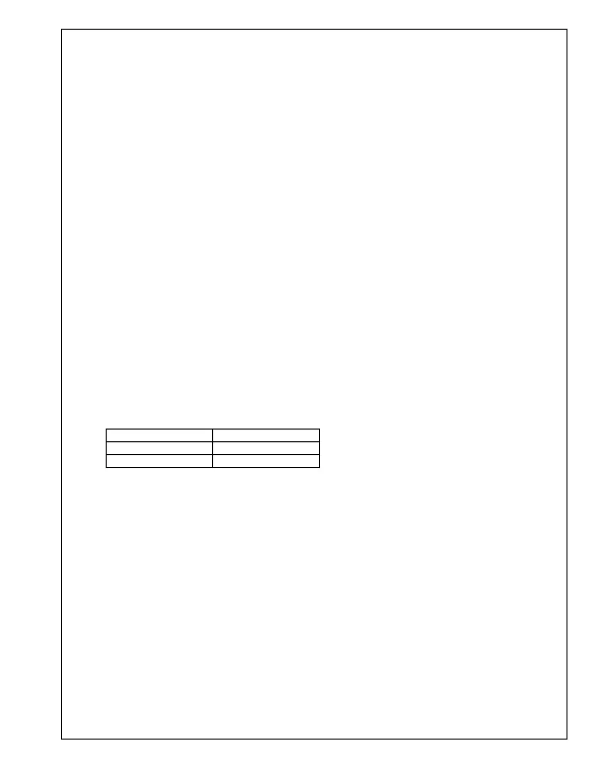
2.3 Measure the response according to the following table:
3. DC Offset
Take this measurement without applying a source signal.
3.1 Connect a DC meter to the amplifier's output.
3.2 There should be ≤ 50 mVDC at the amplifier output.
TEST PROCEDURES
Frequency Output
20 Hz ± .75 dB
20 kHz ± .75 dB
 Loading...