14
A pair of signal relays, K5000 [sheet 13, C2] and K5001 [B2], permit selection of internally
generated Composite and S-Video signals or pass-through of external Composite and S-Video
signal inputs to the output Composite and S-Video connector J201. When VIDEO_SEL is low,
the console is configured as video pass-through mode which plays external video signals.
When VIDEO_SEL is high, the console is configured as playing video signals from CS98200.
The Component Video (YPrPb) output should be selected whenever the COMP_SENSE signal
is high. Also, when Component Video is selected, the VIDEO_SEL line shall remain low at all
times. This prevents attenuation of the video signal if both sets of outputs (Composite, S-Video
and YPrPb) are connected to other equipment.
6. Tuner Electronics
The tuner function is implemented on a dedicated PCB which has no other essential functions
or hardware. This has the advantage of the console working without needing the tuner board in
circuit. The topology of the tuner circuit itself is very similar to the 321 Series I tuner. There are
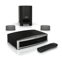
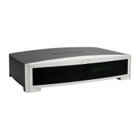
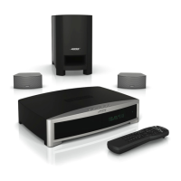
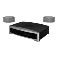
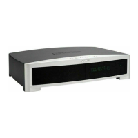
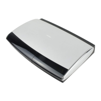
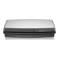
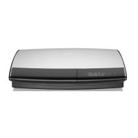
three variations of the final assembly. See SD270575 for details.
Note: Refer to the Tuner PCB schematic sheets, 270575, for the following information.
6.1 Main PCB Interface
Interfacing the Tuner PCB to the Main is accomplished through a 13 connection flat-flex cable to
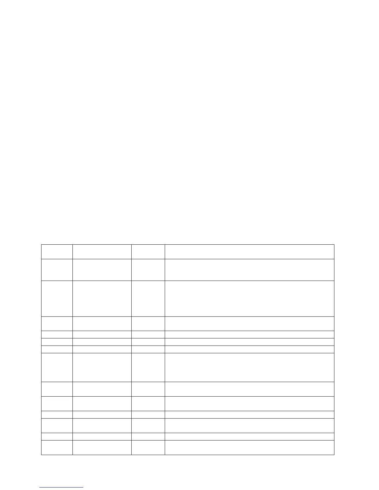
connector J1 [sheet 2, C8]. Below is a table describing the pin functionality…
THEORY OF OPERATION
Pin
Number
Name Direction Function/Notes
1 +12V Supply Sole supply voltage for the tuner board, in normal
operation it draws <100mA. Local 10V(U18) and 5V(U19)
is derived from this
2 Supply_Freq_Sel Output Logic Level output setting the main board switching power
supply frequency determined by a lookup table in the ST
micro (ST72324) for interference avoidance. AM only.
Low, Fsync=97.324kHz
High, Fsync=100.800kHz
3 Gnd Supply Return for all signals. No differentiation in grounding is
implemented on the tuner board.
4 Tuner_L Output Left channel analog audio output.
5 Tuner_R Output Right channel analog audio output.
6 Gnd Supply As 3
7 Tnrbd_Sel Input Buffered SPI select line for communicating with the
ST72324 from the CS98200 on the main board. Note, this
comm bus is shared with the display so this line allows for
the differentiation of commands between systems.
8 Tnrbd_Clk Input Buffered SPI clock line for communicating with the
ST72324 from the CS98200 on the main board.
9 Tnrbd_Datain Output SPI data from the ST72324 to the CS98200. +5V logic
levels.
10 Gnd Supply As 3
11 Tnrbd_Dataout Input Buffered SPI data output from the CS98200 to the
ST72324.
12 Tnrbd_Reset Input Hard Resets the ST72324
13 Tnrbd_Flash Input Control Signal to apply programming voltage to ST72324 in
order to reprogram internal flash.
 Loading...