4
THEORY OF OPERATION
System Overview
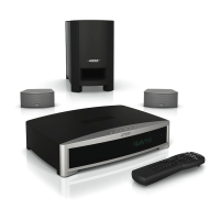
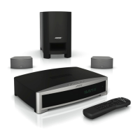
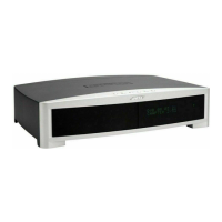
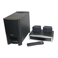
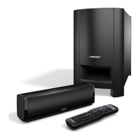
The 3
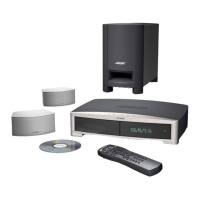
•2•1 Series II is a single-zone home entertainment system. It has two configurations:
(1) basic/standard system with no Ethernet interface and no hard drive or uMusic
TM
function.
This system will be available with either the standard 3
•2•1 speaker arrays or the Gemstone
TM
speaker arrays. (2) A premium system including the Ethernet interface and hard drive and
uMusic. This system will also incorporate the array speakers developed in the Gemstone
project.
The 3
•2•1 Series II system consists of the following major components:
1. Console with Display, Main board, Tuner board, button board and IR remote receiver,
CD/DVD driver, Hard disk driver (premium version only).
2. Bass module Unit with Woofer, DSP board, I/O board and system power supply.
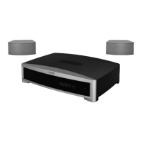
3. Two two-element speaker arrays.
4. IR remote control.
Console Theory of Operation
The basic elements of the console are:
1. Main board.
2. Tuner board.
3. VFD display.
4. DVD ROM driver.
5. Button board.
6. IR receiver.
7. Hard disk driver (premium only)
8. Ethernet interface (premium only)
1. Power Supply
Note: Refer to the 3
•2•1 II console schematic sheets, 270593, for the following information.
The bass module provides un-regulated power V_UNREG to console via connector J100 pins 1
and 2 [sheet 10, B2]. The power supply electronics are comprised of 4 main sections; switching
power supplies, linear power supplies, power supply synchronization, and power fail detection.
The console’s input voltage, V_UNREG, comes from the bass module and is nominally 26VDC.
This voltage varies with load and line levels, but is limited to 31.5V maximum (assuming line
voltage of 140V AC). This voltage is always present whenever the bass module is plugged into
the wall and so the console’s power supplies are likewise active. All the voltage level source are
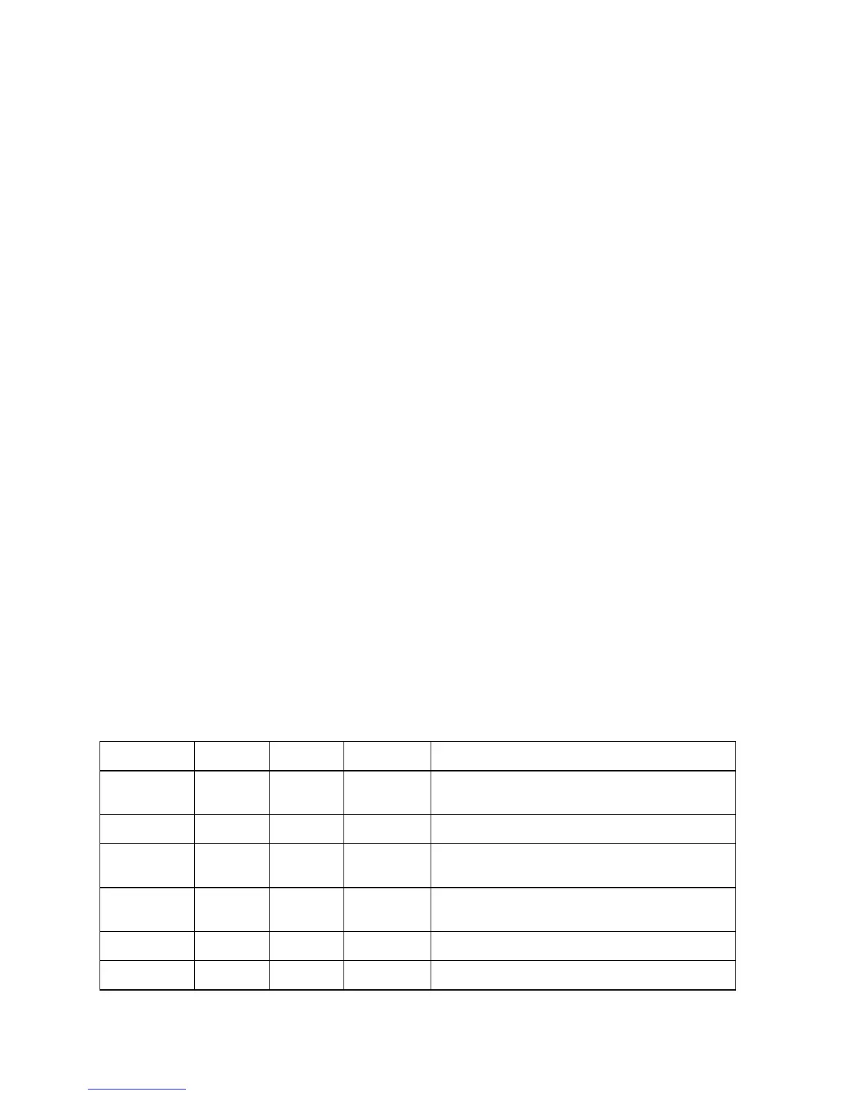
listed in following table:
Note: The 1.8V and 3.3V linear regulators are derived from the +5V switching power supply.
The 9V linear regulator is derived from the +12V switching power supply.
Node Name Output
Voltage
Type Input from Outputs to
V_UNREG +26 Full wave
rectifier
Bass module
at line of
120VAC
+12V and +5V switching power supply
+12V +12 Switching V_UNREG DVD drive, Tuner board, VFD display, Video control
relay.
+9V +9 Linear +12V Analog MUX, DAC output filter op-amps, Summing
op-amps and Zone speaker differential input op-
amps.
+5V +5 Switching V_UNREG +3.3V and +1.8V switching power supply; DVD
drive, Hard disk driver, IR receiver, DAC, SPDIF
receiver.
+3.3V +3.3 Linear +5V Processor CS98200’s I/O power, Flash, SDRAM
IC’s, Ethernet controller, SPDIF receiver,
+1.8V +1.8 Linear +3.3V Processor CS98200’s core and PLL circuit power;
power on/monitor reset chip.
 Loading...