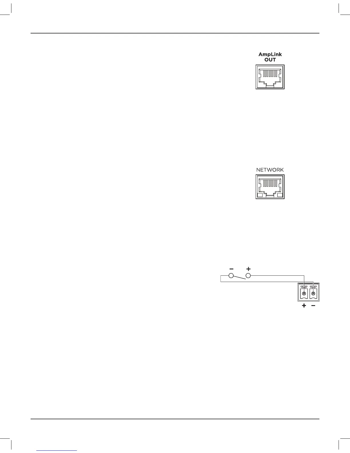
AmpLink Connection
The AmpLink Out port provides a low-latency method for transporting
up to eight channels of uncompressed digital audio to AmpLink-
compatible amplifiers. For simplified audio distribution, the CSP-428
and CSP-1248 can also serve as centralized input-routing/mixing
points to one or more AmpLink-compatible amplifiers when installed
in the same rack. Each amplifier must have a built-in AmpLink port or
an AmpLink 24-channel input card installed.
Use shielded EIA/TIA 568B straight Cat 5 cables (or equivalent) to make
this connection. You can daisy-chain up to eight AmpLink-compatible
products with up to 10 meters (32 feet) of cable between each product.
CAUTION: Shielded EIA/TIA 568B straight Cat 5 cables (or equivalent)
are required for proper AmpLink operation. Unshielded cables are not
supported and may cause AmpLink audio to operate improperly. Do
not connect an AmpLink port to an Ethernet-based network.
CC-1D/CC-2D/CC-3D
The ControlCenter CC-1D, CC-2D, and CC-3D can be used for volume
and mute control. The CC-2D and CC-3D can also be used for source
control. You can connect these controllers to the Network port via a
PoE network switch (not included). You can connect up to
16 controllers or up to 32 controllers, depending on the amplifier you
are using with the CSP.
Use a foiled or unshielded twisted-pair (F/UTP) Cat 5e cable (not
included) to connect this port on each CSP to your network or
computer. Make this connection directly to the CSP or through a
switched Ethernet network.
See Overview > Available Accessories (page 11) for a list of
compatible accessories.
Mute with Standard Contact Closure
The CSP-428 and CSP-1248 are designed to mute all outputs either
when the Mute contacts are either shorted together or opened,
depending on how the CSP is configured.
The default state is Normally Open (NO), where a short across the
mute connector will mute all outputs. Using the CSP integrated web
server, the mute polarity can be inverted to Normally Closed (NC),
where an open across the mute connector will mute all outputs.
Note: All LED indicators will blink red when the amplifier is muted from
software or from the rear panel Mute connector.
Use the included black 2-pin Euroblock to make this connection.
 Loading...