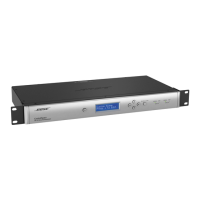
CSP-1248
Integrated DSP
Signal Process/CPU 32-bit fixed/floating-point DSP + Arm®, 456 MHz
Maximum Calculation 3.6 GIPS / 2.7 GFLOPS
Audio Latency 900 μs (analog in to analog out)
A/D and D/A Converters 24-bit
Sample Rate 48 kHz
Audio Performance
Frequency Response 20 Hz to 20 kHz (±0.5 dB)
THD+N < 0.01% at +4 dBu (A-weighted/20 Hz to 20 kHz)
Channel Separation (Crosstalk) < –105 dB at +4 dBu input and output level, 1 kHz
Dynamic Range 115 dB A-weighted 20 Hz to 20 kHz, analog through, 600 Ώ load
Audio Inputs
Inputs (balanced) 8 analog (balanced, Mic/Line Level/Page-In)
Inputs (unbalanced) 4 analog (unbalanced, RCA Line-In, summed to mono)
Connectors, Input Balance Input: green 3.81 mm pitch (3-pin/6-pin)
Page-In: green 3.81 mm pitch (4-pin)
Unbalanced Input: red/white RCA connector
Input Impedance 12 kΩ at 1 kHz (with or without phantom power active)
Maximum Input Level +24 dBu (THD+N ≤0.3%, 20 Hz to 20 kHz, 0 dB gain)
Equivalent Input Noise < –117 dBu (22 Hz to 20 kHz, 150 Ω input, 64 dB gain)
Phantom Power +48V, open circuit, 10 mA max per channel, selectable per input, 80 mA
max across all channels
Pre-Gain Settings 0/14/24/32/44/54/64 dB
Audio Outputs
Outputs 2 analog (balanced, Line Level), 8 digital (AmpLink output)
Connectors, Output Analog Output: orange 3.81 mm pitch (6-pin)
Digital Output: RJ-45 without LED (AmpLink output)
Output Impedance 66 Ω
Maximum Output Level +24 dBu (THD+N ≤0.3%, 22 Hz to 20 kHz )
Control Inputs
Inputs (Control) 8 analog inputs, 2 kΩ internal pull-up resistor to 5 V, green 3.81 mm pitch
connector (9-pin)
Mute (Control) 1 analog input, 2 kΩ internal pull-up resistor to 5 V, black 3.81 mm pitch
connector (2-pin)
Analog Input Voltage 0 V to 3.3 V (maximum 5 V)
Digital Input Voltage 0 V to 3.3 V (threshold voltage = 1.6 V)
Control Outputs
Outputs (Control) 1 digital output, orange 3.81 mm pitch connector (2-pin)
Output Voltage High: 8 V (open circuit), 2.5 V at 10 mA, Low: < 1 V at 100 mA, push-pull
Output Current 10 mA source, 100 mA sink (24 VDC max external supply voltage)
Indicators and Controls
LED Status Indicators Power/Status, Signal, Ethernet, AmpLink
Audio Signal Indication Green (–60 to –20 dBFS), yellow (–20 to –2 dBFS), red (–2 dBFS to Clip)
 Loading...