4
DISASSEMBLY/ASSEMBLY PROCEDURES
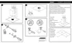
Note: Refer to Figure 1 for the following
procedures.
1. Terminal Plate Removal
1.1 Remove the six screws (3) securing the
terminal plate (2) to the bass module (1).
1.2 Gently lift and rotate the terminal plate
(2) so you can access the harness. Untwist
the service loop in the harness so the
crossover assembly (13) can be accessed.
2. Terminal Plate Replacement
2.1 Place the terminal plate (2) onto the
bass module. Twist the wire harness into a
service loop.
2.2 Secure the terminal plate (2) to the
bass module using the six screws (3).
3. Crossover Assembly Removal
3.1 Perform procedure 1.
3.2 Remove the four screws (4) securing
the crossover assembly (13) to the terminal
plate (2).
3.3 Gently lift the crossover assembly (13)
off of the tabs on the terminal plate (2).
4. Crossover Assembly Replacement
4.1 Place the crossover assembly (13) onto
the terminal plate (2) and gently push it on
to the tabs.
4.2 Secure the crossover assembly (13) to
the terminal plate (2) using four screws (4).
4.3 Perform procedure 2.
5. Woofer Removal
5.1 The woofer is not accessible and
therefore the bass module assembly is not
repairable.
6. Transformer Removal
6.1 Preform procedure 1.
6.2 Disconnect the connector at J3.
6.3 Using a 11/32" nutdriver remove the
two nuts (2) that secure the transformer to
the terminal plate (2).
6.4 Remove the transformer from the studs
on the terminal plate.
7. Transformer Replacement
7.1 Place the transformer (3) onto the studs
on the terminal plate (2).
7.2 Using a 11/32" nutdriver secure the
transformer (3) to the terminal plate (2)
using the nuts (2).
7.3 Preform procedure 2.
8. 70/100 Volt Input Connector Removal
8.1 Remove the two screws (6) that secure
the connector (10) to the terminal plate (2).
8.2 Lift the connector up off of the terminal
plate. You might need to use a flatblade
screwdriver to gently pry the connector up.
9. 70/100 Volt Input Connector
Replacement
9.1 Place the connector (10) over the
terminal plate (2) and while aligning the
pins to the crossover PCB gently push the
connector into place.
9.2 Secure the connector to the terminal
plate using the screws (6).

 Loading...