14
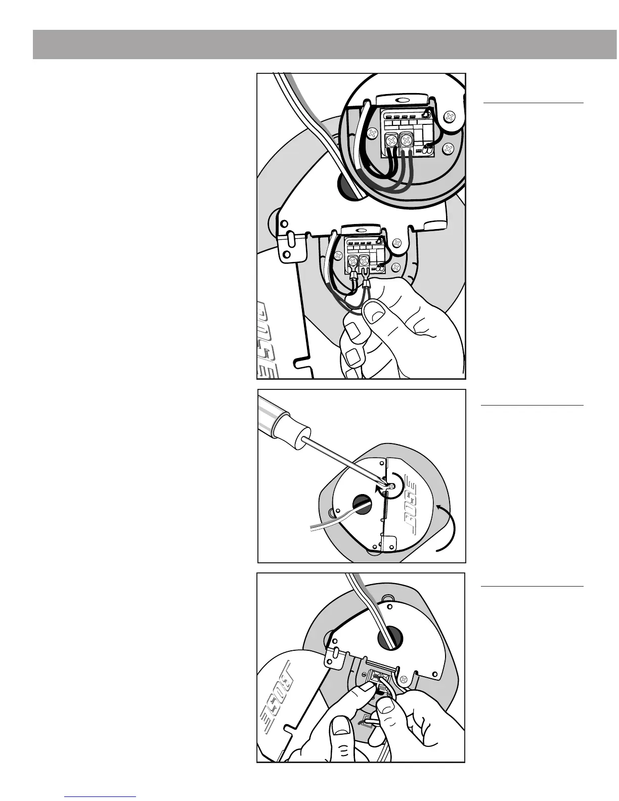
Figures 18a
and 18b
4.0 Installation
Figure 18a
Figure 18b
4.3 Electrical connections
70V and 100V versions
1a. For stripped wire connections,
place one straight wire on each
side of the screw beneath the
screw plate. Tighten the screw
(Figure 18a).
1b. For crimp-on forked connectors,
slide the connector under the
screw plate. Tighten the screw
(Figure 18b).
2. Close the cover and tighten the
screw (Figure 19).
Note: If the screw is loose the cover
will make a vibrating noise.
4Ω version
1. Depress the terminal tab.
2. Insert the stripped end of wires
(Figure 20).
3. Close the loudspeaker cover and
tighten the screw (see Figure 19).
Figure 19
Figure 20
CAUTION
Using forked connectors for multiple
wires (as shown in Figure 18b) is not
allowed in fire protective signaling and
warning systems due to the lack
of electrical supervision capability.
CAUTION
For 70V loudspeakers, be sure the
appropriate UL listed
1
/
2
"
trade size wire
fitting is installed. (See Section 3.4
“Junction box fittings”)
AM177915_03_V.pdf • May 6, 2002
 Loading...