English User Guide Page 19
pro.Bose.com Installation and Operating Guide
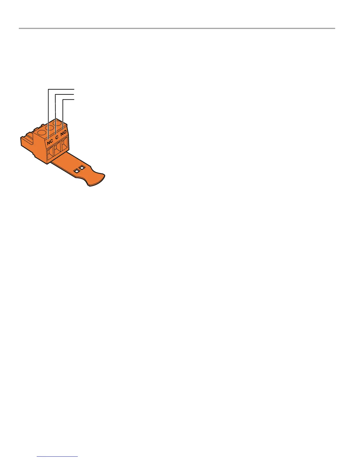
Fault Notification Output
Each PowerMatch amplifier features a hardware fault notification circuit. This circuit drives a normally open or normally closed contact
closure (1A, 30 VDC maximum). The fault output, using the orange-colored 3-pin terminal block (Phoenix Contact #1976010, supplied),
is intended to provide an external connection to a remote system monitor for fault notification purposes. Terminal assignments are
printed directly on the connector as shown in Figure 7. See "About the Alarm Log and Fault Indicator" on page 38 for details on
trapped faults and how to filter reported faults.
Figure 7. Fault Notification output connector
Normally closed
Common
Normally open
Serial over Ethernet
Network version amplifiers can leverage the Ethernet connector to communicate serial data with control systems and devices.
Commands are available to read and set Standby Mode status, and to read the output configuration. For interfacing with third party
control systems, the amplifier is also able to read and set the amplifier to broadcast alarms, fault events, and changes to the Fault
Output state when they occur.
A full listing of the available protocol can be found in the PDF document "ControlSpace Serial Control Protocol" on pro.Bose.com.
 Loading...