7
Power Wiring Interconnections
All wiring must be the proper size, properly supported
and protected by conduit. All wiring should be done per
applicable federal, state and local codes, standards and
regulations. Obey wire type and torque specifications printed
on the terminal blocks and neutral/ground connector.
Complete the following connections between the transfer
switch, main distribution panel, utility power and generator.
Useunstaller-supplied300VACorgreaterwirethatcomplies
with Table 310.16 in the National Electric Code. Apply the
necessary correction factors and wire size calculations.
1. Set generator’s system switch to OFF position.
2. Set generator’s circuit breaker to OFF (open) position.
3. Turn off utility power to the standby generator and
transfer switch.
4. Connect utility service to transfer switch service
disconnect circuit breaker terminals marked
“UTILITY CONNECTION”.
5. Connect utility service neutral to transfer switch
neutral terminal.
6. Connect main distribution panel feeder
conductors to transfer switch terminals marked
“LOAD CONNECTION”.
7. Connect main distribution panel neutral conductor to
transfer switch neutral terminal.
8. Connect main distribution panel ground conductor to
transfer switch “GND” terminal.
NOTE: Assure grounding electrode conductor is connected
and bonded per applicable federal, state and local codes,
standards and regulations.
9. Connect copper feeder conductors from transfer
switch breaker “GENERATOR CONNECTION” terminals
to generator control panel breaker. Each conductor
must pass through hole of current transformer before
making connection.
10. Plug current transformer leads into “CT1” and “CT2”
terminals on control module.
11. Connect copper conductor from transfer switch neutral
terminal to generator control panel neutral terminal.
12. Connect copper conductor from transfer switch “GND”
terminal to generator control panel “GROUND” terminal.
NOTE: Assure generator equipment grounding conductor
is connected per applicable federal, state and local codes,
standards and regulations.
13. Connectthetransferswitch“UTILITY240VAC”
terminalstogenerator’s“240VAC”terminals
usinginstallersupplied300VACorgreatercopper
wire, minimum #14 AWG conductors via supplied
two-pole connector.
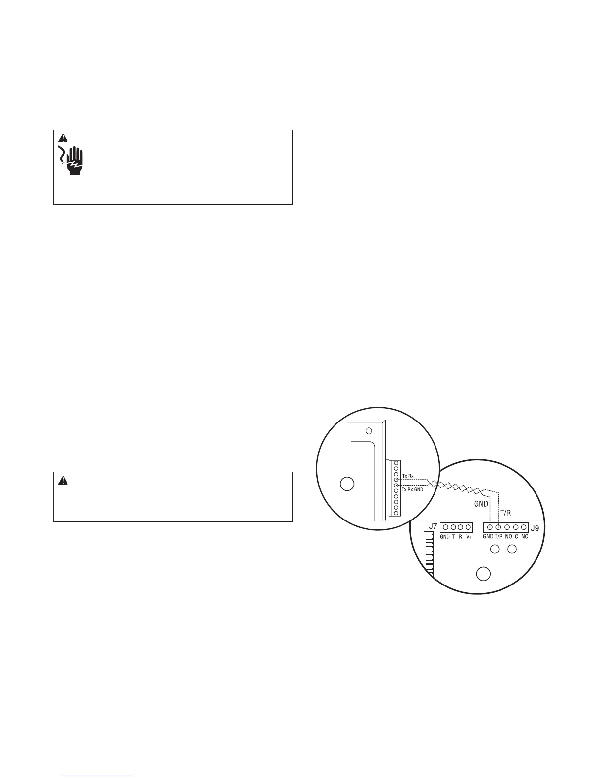
14. Connect “GND” and “T/R” terminals on transfer
switch control board (B) to the generator’s control
panel (A) “TxRx” and “TxRx GND” terminals using
#18 AWG twisted pair copper conductors, no greater
than 200 ft in length, 300 volt 75°C-90°C via supplied
ten-pole connector.
15. Tighten all wire connections/fasteners to proper torque.
See label inside transfer switch enclosure for proper
torque values.
• Whenconnectingtocircuitboardterminalblocks,
fasten only one wire to each connector screw.
• Torqueterminalblockscrewsto12in-lb
(13.5 Newton meter).
The illustration on page 8 shows a typical completed
installation. The actual layout will vary.
WARNING Low voltage wire cannot be installed in
same conduit as power voltage wiring.
Failure to follow above warning could cause personal •
injury, damage and/or malfunction of equipment.
NOTICE Improper installation can cause damage to the
circuit boards and shorten their life. Installing circuit
boards in live circuits will damage the board and is not
covered by warranty. ALWAYS disconnect ALL sources of
power prior to servicing.
Remove all power prior to installing this equipment. •
Failure to do so could cause internal damage to the board
when making electrical connections.
Turn generator to • OFF position.
Turn off utility power to the standby generator and •
transfer switch.
WARNING Battery posts, terminals and related
accessories contain lead and lead compounds, chemicals
known to the State of California to cause cancer and
reproductive harm. Wash hands after handling.
A
B
 Loading...