Wiring Interconnections
All wiring must be the proper size, properly supported and
protected by conduit.
Complete the following connections between the transfer
switch, main distribution panel, utility power and generator,
as shown on the next page.
High Voltage Wiring
1. Ensure utility power is turned OFF. Connect utility
power supply leads to transfer switch terminals marked
“UTILITY CONNECTION”.
2. Connect utility neutral to the transfer switch
“NEUTRAL” terminal.
3. Connect main distribution panel power leads to transfer
switch terminals marked “LOAD CONNECTION”.
4. Connect main distribution panel neutral lead to transfer
switch “NEUTRAL” terminal.
5. Connect generator power supply leads from the
generator’s control panel to transfer switch terminals
marked “GENERATOR CONNECTION”. Each lead should
pass through hole of current transformer before
connection to contactor.
6. Plug in current transformer leads into “CT1” and “CT2”
on control module.
7. Connect generator Neutral from the control panel to the
transfer switch “NEUTRAL” terminal.
8. Connect generator “GND” from the control panel to the
transfer switch “GND” terminal.
9. Connect main distribution panel “GND” to the transfer
switch “GND” terminal.
NOTE: Assure grounding electrode conductor is connected
and bonded per applicable federal, state and local codes,
standards and regulations.
10. Connect generator utility 240 VAC terminals to transfer
switch utility 240 VAC terminals.
11. Tighten all wire connections/fasteners to proper torque.
See inside transfer switch enclosure for proper torque
values.
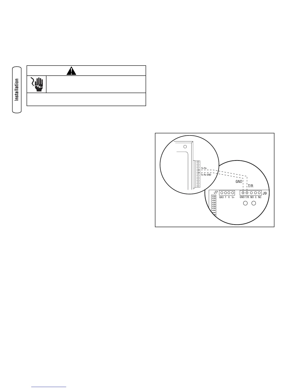
Low Voltage Wiring
1. Connect Tx Rx and Tx Rx Ground from the generator
control panel to the GND and T/R on the transfer switch
control board.
2. Tighten all wire connections/fasteners to proper torque.
See inside transfer switch enclosure for proper torque
values.
8 BRIGGSandSTRATTON.COM
WARNING
Low voltage wire cannot be installed in same
conduit as power voltage wiring.
• Failure to follow above warning could cause personal injury,
damage and/or malfunction of equipment.
 Loading...