


Do you have a question about the Brother MFC-8510DN and is the answer not in the manual?
| Print technology | Laser |
|---|---|
| Maximum resolution | 1200 x 1200 DPI |
| Economical printing | Yes |
| Duplex printing mode | Auto |
| Time to first page (black, normal) | 8.5 s |
| Print speed (black, normal quality, A4/US Letter) | 36 ppm |
| Duplex print speed (black, normal quality, A4/US Letter) | 9 ppm |
| PictBridge | No |
| Scan speed | 2.68 sec/page |
| Dimensions (WxDxH) | 405 x 415 x 423 mm |
| All-in-one functions | Copy, Fax, Print, Scan |
| Color all-in-one functions | Scan |
| Printing colors | Black |
| Maximum duty cycle | - pages per month |
| Recommended duty cycle | 500 - 3500 pages per month |
| Page description languages | BR-Script 3, Epson FX, IBM ProPrinter, PCL 6 |
| Copier resize | 25 - 400 % |
| Maximum copy resolution | 1200 x 600 DPI |
| Maximum number of copies | 99 copies |
| N-in-1 copy function (N=) | 2, 4, 9, 16, 25 |
| Time to first copy (black, normal) | 10.5 s |
| Copy speed (black, normal quality, A4) | 36 cpm |
| Scan to | E-mail, E-mail Server, File, FTP, Image, OCR, USB |
| Scan drivers | ICA, ISIS, TWAIN |
| Scanner type | Flatbed & ADF scanner |
| Grayscale levels | 256 |
| Input color depth | 48 bit |
| Maximum scan area | Legal (216 x 356) mm |
| Output color depth | 24 bit |
| Image formats supported | BMP, JPG |
| Maximum scan resolution | 19200 x 19200 DPI |
| Document formats supported | |
| Faxing | Mono faxing |
| Fax memory | 500 pages |
| Modem speed | 33.6 Kbit/s |
| Fax coding methods | JBIG, JPEG, MH, MMR (Fax coding method), MR |
| Fax speed dialing (max numbers) | 300 |
| Paper input type | Paper tray |
| Total input capacity | 250 sheets |
| Total output capacity | 150 sheets |
| Maximum input capacity | 850 sheets |
| Total number of input trays | 1 |
| Maximum number of input trays | 2 |
| Multi-Purpose tray input capacity | 50 sheets |
| Auto document feeder (ADF) input capacity | 35 sheets |
| Custom media width | 76.2 - 215.9 mm |
| Maximum print size | 216 x 356 mm |
| Custom media length | 127 - 355.6 mm |
| Paper tray media types | Bond paper, Plain paper, Pre-Printed, Recycled paper, Thin paper |
| Paper tray media weight | 60 - 105 g/m² |
| Non-ISO print media sizes | Legal |
| ISO A-series sizes (A0...A9) | A4, A5, A6 |
| ISO B-series sizes (B0...B9) | B5, B6 |
| Multi-purpose tray media types | Bond paper, Envelopes, Heavyweight paper, Labels, Plain paper, Preprinted forms, Recycled paper |
| Maximum ISO A-series paper size | A4 |
| Multi-Purpose Tray media weight | 60 - 163 g/m² |
| Auto Document Feeder (ADF) media weight | 64 - 90 g/m² |
| Display | LCD |
| Market positioning | Home & office |
| Display number of lines | 5 lines |
| Display number of characters | 22 |
| Standard interfaces | Ethernet, USB 2.0 |
| Security algorithms | 802.1x RADIUS, EAP, EAP-TLS, EAP-TTLS, MD5, PEAP |
| Internal memory | 64 MB |
| Processor family | Star Sapphire |
| Maximum internal memory | 320 MB |
| Sound power level (standby) | 37 dB |
| Sound pressure level (printing) | 59 dB |
| Sound pressure level (quiet mode) | 54 dB |
| AC input voltage | 220 - 240 V |
| AC input frequency | 50 - 60 Hz |
| Power consumption (off) | 1.2 W |
| Power consumption (standby) | 8.1 W |
| Power consumption (PowerSave) | 336 W |
| Power consumption (average operating) | 651 W |
| Package weight | 20.100 g |
| Sustainability certificates | ENERGY STAR |
Lists the specifications for each model, including general details, connectivity, supplies, and paper handling.
Provides an overview of troubleshooting procedures and essential precautions before starting repairs.
Details the machine's components, including cross-section drawings, paper feeding paths, and block diagrams.
Lists and explains error messages and codes displayed by the machine's self-diagnostic function.
Provides essential warnings and precautions to avoid secondary problems during maintenance work.
Details the procedures for installing firmware, setting country, initializing EEPROM, and adjusting touch panel.
Explains the maintenance mode for checking settings, adjustments, and sensors using control panel buttons.
Provides the wiring diagram for the connections of the PCBs within the machine.
Lists the specifications for each model, including general details, connectivity, supplies, and paper handling.
Details the paper input, output, and duplex handling capabilities for various models.
Specifies the types of paper and media weights supported for different input sources.
Lists the paper tray names and their corresponding names in the printer driver.
Provides an overview of troubleshooting procedures and essential precautions before starting repairs.
Details the machine's components, including cross-section drawings, paper feeding paths, and block diagrams.
Lists and explains error messages and codes displayed by the machine's self-diagnostic function.
Provides detailed procedures for diagnosing and resolving common problems.
Provides an overview of troubleshooting procedures and essential precautions before starting repairs.
Provides an overview of troubleshooting procedures and essential precautions before starting repairs.
Provides an overview of troubleshooting procedures and essential precautions before starting repairs.
Details the machine's components, including cross-section drawings, paper feeding paths, and block diagrams.
Details the machine's components, including cross-section drawings, paper feeding paths, and block diagrams.
Details the machine's components, including cross-section drawings, paper feeding paths, and block diagrams.
Details the machine's components, including cross-section drawings, paper feeding paths, and block diagrams.
Details the machine's components, including cross-section drawings, paper feeding paths, and block diagrams.
Details the machine's components, including cross-section drawings, paper feeding paths, and block diagrams.
Details the machine's components, including cross-section drawings, paper feeding paths, and block diagrams.
Details the machine's components, including cross-section drawings, paper feeding paths, and block diagrams.
Details the machine's components, including cross-section drawings, paper feeding paths, and block diagrams.
Details the machine's components, including cross-section drawings, paper feeding paths, and block diagrams.
Details the machine's components, including cross-section drawings, paper feeding paths, and block diagrams.
Lists and explains error messages and codes displayed by the machine's self-diagnostic function.
Provides descriptions for various error messages displayed on the machine's LCD.
Details communication error codes related to fax and network operations.
Provides detailed procedures for diagnosing and resolving common problems.
Provides detailed procedures for diagnosing and resolving common problems.
Provides detailed procedures for diagnosing and resolving common problems.
Provides detailed procedures for diagnosing and resolving common problems.
Provides detailed procedures for diagnosing and resolving common problems.
Provides detailed procedures for diagnosing and resolving common problems.
Provides detailed procedures for diagnosing and resolving common problems.
Provides detailed procedures for diagnosing and resolving common problems.
Provides detailed procedures for diagnosing and resolving common problems.
Provides detailed procedures for diagnosing and resolving common problems.
Provides detailed procedures for diagnosing and resolving common problems.
Provides detailed procedures for diagnosing and resolving common problems.
Provides detailed procedures for diagnosing and resolving common problems.
Provides detailed procedures for diagnosing and resolving common problems.
Provides detailed procedures for diagnosing and resolving common problems.
Provides detailed procedures for diagnosing and resolving common problems.
Provides detailed procedures for diagnosing and resolving common problems.
Provides detailed procedures for diagnosing and resolving common problems.
Provides detailed procedures for diagnosing and resolving common problems.
Provides detailed procedures for diagnosing and resolving common problems.
Provides detailed procedures for diagnosing and resolving common problems.
Provides detailed procedures for diagnosing and resolving common problems.
Provides detailed procedures for diagnosing and resolving common problems.
Provides detailed procedures for diagnosing and resolving common problems.
Provides detailed procedures for diagnosing and resolving common problems.
Provides detailed procedures for diagnosing and resolving common problems.
Provides detailed procedures for diagnosing and resolving common problems.
Provides detailed procedures for diagnosing and resolving common problems.
Provides detailed procedures for diagnosing and resolving common problems.
Provides detailed procedures for diagnosing and resolving common problems.
Provides detailed procedures for diagnosing and resolving common problems.
Guides users through common paper feeding issues like multiple sheets or wrinkled paper.
Guides users through common paper feeding issues like multiple sheets or wrinkled paper.
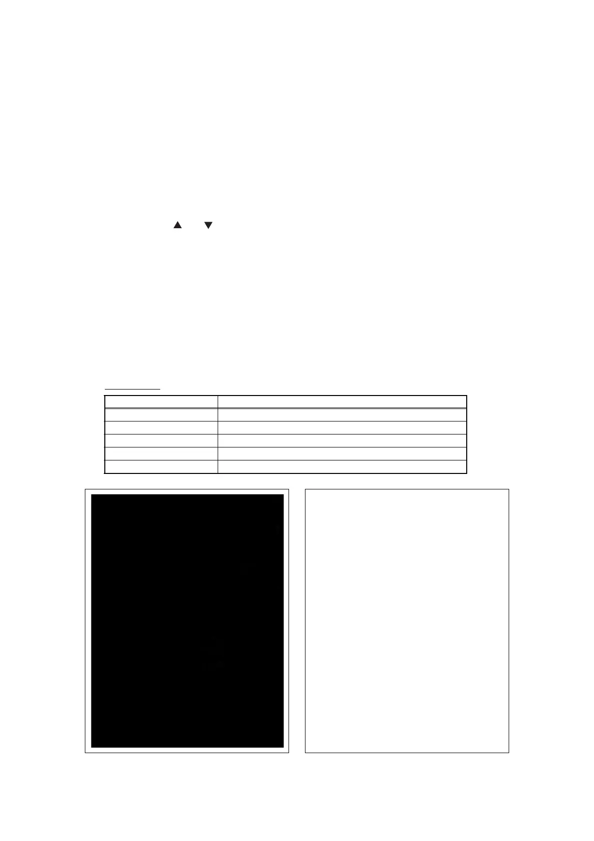
Provides examples and troubleshooting steps for various image quality issues.
Provides examples and troubleshooting steps for various image quality issues.
Provides examples and troubleshooting steps for various image quality issues.
Provides examples and troubleshooting steps for various image quality issues.
Provides examples and troubleshooting steps for various image quality issues.
Provides examples and troubleshooting steps for various image quality issues.
Provides examples and troubleshooting steps for various image quality issues.
Provides examples and troubleshooting steps for various image quality issues.
Provides examples and troubleshooting steps for various image quality issues.
Provides examples and troubleshooting steps for various image quality issues.
Provides examples and troubleshooting steps for various image quality issues.
Provides examples and troubleshooting steps for various image quality issues.
Provides examples and troubleshooting steps for various image quality issues.
Guides users on resolving software-related issues, such as inability to print.
Provides steps for resolving issues related to network connectivity and printing.
Offers solutions for issues with the LCD display and control panel operation.
Addresses issues related to toner detection, cartridge errors, and drum unit problems.
Provides troubleshooting steps for fuser unit failures.
Offers solutions for laser unit failures.
Guides on troubleshooting issues related to Main PCB, High-voltage, and Low-voltage PCBs.
Provides solutions for document feeding issues like multiple sheets or incorrect size detection.
Provides examples and troubleshooting steps for various image quality issues.
Provides examples and troubleshooting steps for various image quality issues.
Provides examples and troubleshooting steps for various image quality issues.
Offers solutions for common fax issues like sending failures, receiving problems, or communication errors.
Addresses miscellaneous issues such as machine not turning on or unusual noises.
Provides essential warnings and precautions to avoid secondary problems during maintenance work.
Details the step-by-step procedures for disassembling various machine parts.
Details the step-by-step procedures for disassembling various machine parts.
Details the step-by-step procedures for disassembling various machine parts.
Provides essential warnings and precautions to avoid secondary problems during maintenance work.
Illustrates the routing and connections of harnesses for the Main PCB.
Details the routing and connections of harnesses for the Relay front PCB.
Illustrates the harness routing and connections for the Fuser unit.
Details harness routing and connections for the High-voltage power supply PCB.
Shows harness routing and connections for the Toner LED PCB and Main fan.
Illustrates harness routing and connections for the Laser unit.
Details harness routing and connections for the Low-voltage power supply PCB.
Illustrates harness routing and connections for the NCU PCB and Speaker unit.
Shows harness routing and connections for Wireless LAN and USB host PCBs.
Details harness routing and connections for the Panel PCB.
Illustrates harness routing and connections for the Main frame R.
Details disconnecting cables and removing accessories before disassembly.
Provides step-by-step instructions for removing and disassembling Paper tray 1.
Details the procedure for removing the back cover and outer chute.
Provides instructions for removing the fuser cover.
Details the procedure for removing the MP cover Assy and related parts.
Provides instructions for removing the front cover Assy and its components.
Details the procedure for removing the Side cover L and Access cover.
Provides instructions for removing the Side cover R Assy.
Details the procedure for removing the ADF unit and its related components.
Details the procedure for removing the ADF unit and its related components.
Details the procedure for removing the ADF unit and its related components.
Details the procedure for removing the ADF unit and its related components.
Details the procedure for removing the ADF unit and its related components.
Details the procedure for removing the ADF unit and its related components.
Details the procedure for removing the ADF unit and its related components.
Details the procedure for removing the ADF unit and its related components.
Details the procedure for removing the ADF unit and its related components.
Details the procedure for removing the ADF unit and its related components.
Details the procedure for removing the ADF unit and its related components.
Details the procedure for removing the ADF unit and its related components.
Details the procedure for removing the ADF unit and its related components.
Details the procedure for removing the ADF unit and its related components.
Details the procedure for removing the ADF unit and its related components.
Details the procedure for removing the ADF unit and its related components.
Details the procedure for removing the ADF unit and its related components.
Details the procedure for removing the ADF unit and its related components.
Details the procedure for removing the ADF unit and its related components.
Details the procedure for removing the ADF unit and its related components.
Details the procedure for removing the ADF unit and its related components.
Details the procedure for removing the ADF unit and its related components.
Provides instructions for removing the panel cover and printed panel cover.
Provides instructions for removing the panel cover and printed panel cover.
Provides instructions for removing the panel cover and printed panel cover.
Provides instructions for removing the panel cover and printed panel cover.
Provides instructions for removing the panel cover and printed panel cover.
Provides instructions for removing the panel cover and printed panel cover.
Provides instructions for removing the panel cover and printed panel cover.
Details the procedure for removing the document scanner unit.
Details the procedure for removing the document scanner unit.
Details the procedure for removing the document scanner unit.
Details the procedure for removing the document scanner unit.
Details the procedure for removing the document scanner unit.
Details the procedure for removing the document scanner unit.
Details the procedure for removing the document scanner unit.
Provides instructions for removing the joint cover.
Details removing Wireless LAN PCB Assy and USB host PCB Assy.
Provides instructions for removing the speaker unit.
Details the procedure for removing the NCU PCB Assy.
Provides instructions for disconnecting harnesses and removing the Main PCB Assy.
Provides instructions for disconnecting harnesses and removing the Main PCB Assy.
Details the procedure for removing the fuser unit and its covers.
Details the procedure for removing the fuser unit and its covers.
Details the procedure for removing the fuser unit and its covers.
Provides instructions for removing the laser unit.
Details the procedure for removing the low-voltage power supply PCB Assy.
Details the procedure for removing the low-voltage power supply PCB Assy.
Details the procedure for removing the low-voltage power supply PCB Assy.
Provides instructions for removing the Toner LED PCB Assy.
Provides instructions for removing the Toner LED PCB Assy.
Details the procedure for removing the main fan.
Details the procedure for removing the main fan.
Provides instructions for removing the air duct and filter.
Details the procedure for removing the Relay front PCB Assy.
Provides instructions for removing the Registration clutch and T1 clutch.
Details the procedure for removing the Main frame L Assy.
Details the procedure for removing the Main frame L Assy.
Provides instructions for removing the Main motor Assy.
Provides instructions for removing the Main motor Assy.
Details the procedure for removing the Develop joint gear and Develop joint.
Provides instructions for removing the LT drive gear 29.
Details the procedure for removing the Toner sensor PCB Assy.
Provides instructions for removing the MP solenoid.
Details the procedure for removing the Develop clutch 51R and Develop one way clutch 53.
Provides instructions for removing the new toner actuator.
Details the procedure for removing the internal temperature thermistor.
Provides instructions for removing the fuser drive gear 39.
Provides instructions for removing the fuser drive gear 39.
Details the procedure for removing the duplex solenoid.
Provides instructions for removing the back cover sensor.
Details the procedure for removing the LT connector (T1).
Provides instructions for removing the T1 roller holder Assy.
Details the procedure for removing the High-voltage power supply PCB Assy.
Details the procedure for removing the High-voltage power supply PCB Assy.
Details the procedure for removing the High-voltage power supply PCB Assy.
Provides instructions for removing the Eject sensor PCB Assy.
Details the procedure for removing MP roller holder Assy, MP separation pad Assy, and spring.
Provides instructions for removing T1 paper feed sensor PCB Assy, actuator, and spring.
Provides instructions for removing T1 paper feed sensor PCB Assy, actuator, and spring.
Details the procedure for removing MP paper empty sensor PCB Assy and actuators.
Details the procedure for removing MP paper empty sensor PCB Assy and actuators.
Details the procedure for removing MP paper empty sensor PCB Assy and actuators.
Provides instructions for removing registration sensors, actuators, and springs.
Provides instructions for removing registration sensors, actuators, and springs.
Provides instructions for removing registration sensors, actuators, and springs.
Details the procedure for removing and disassembling Paper tray 2.
Provides instructions for removing the T2 roller holder Assy.
Details the procedure for removing the T2 side cover L.
Provides instructions for removing the T2 side cover R.
Details the procedure for removing the T2 front cover Assy.
Provides instructions for removing the T2 relay PCB Assy.
Details the procedure for removing the T2 clutch.
Provides instructions for removing the T2 paper feed sensor PCB Assy.
Provides instructions for removing the T2 paper feed sensor PCB Assy.
Provides instructions for removing the T2 paper feed sensor PCB Assy.
Provides instructions for removing the T2 paper feed sensor PCB Assy.
Details the procedure for removing the T2 back cover.
Provides instructions for removing the LT connector Assy (T2).
Details the procedures for installing firmware, setting country, initializing EEPROM, and adjusting touch panel.
Details the procedures for installing firmware, setting country, initializing EEPROM, and adjusting touch panel.
Details the procedures for installing firmware, setting country, initializing EEPROM, and adjusting touch panel.
Details the procedures for installing firmware, setting country, initializing EEPROM, and adjusting touch panel.
Details the procedures for installing firmware, setting country, initializing EEPROM, and adjusting touch panel.
Explains how to acquire white level data for the CIS unit.
Provides instructions for adjusting the touch panel detection area.
Details the procedure for entering the adjusted value of the laser unit after replacement.
Details the procedure for entering the adjusted value of the laser unit after replacement.
Explains how to reset the irregular power supply detection counter after replacing the PCB.
Details the procedure for initializing pre-discharge detection parameters after PCB replacement.
Provides instructions for installing panel firmware on touch panel models.
Provides instructions for installing panel firmware on touch panel models.
Provides instructions for adjusting the touch panel detection area.
Details how to check the LCD operation on the control panel.
Explains how to check the operation of control panel buttons.
Explains how to acquire white level data for the CIS unit.
Explains the maintenance mode for checking settings, adjustments, and sensors using control panel buttons.
Explains the maintenance mode for checking settings, adjustments, and sensors using control panel buttons.
Lists all available maintenance mode functions with their corresponding codes and refer to pages.
Provides detailed descriptions and operation procedures for maintenance mode functions.
Provides detailed descriptions and operation procedures for maintenance mode functions.
Provides detailed descriptions and operation procedures for maintenance mode functions.
Provides detailed descriptions and operation procedures for maintenance mode functions.
Provides detailed descriptions and operation procedures for maintenance mode functions.
Provides detailed descriptions and operation procedures for maintenance mode functions.
Provides detailed descriptions and operation procedures for maintenance mode functions.
Provides detailed descriptions and operation procedures for maintenance mode functions.
Provides detailed descriptions and operation procedures for maintenance mode functions.
Provides detailed descriptions and operation procedures for maintenance mode functions.
Provides detailed descriptions and operation procedures for maintenance mode functions.
Provides detailed descriptions and operation procedures for maintenance mode functions.
Provides detailed descriptions and operation procedures for maintenance mode functions.
Provides detailed descriptions and operation procedures for maintenance mode functions.
Provides detailed descriptions and operation procedures for maintenance mode functions.
Provides detailed descriptions and operation procedures for maintenance mode functions.
Provides detailed descriptions and operation procedures for maintenance mode functions.
Provides detailed descriptions and operation procedures for maintenance mode functions.
Provides detailed descriptions and operation procedures for maintenance mode functions.
Provides detailed descriptions and operation procedures for maintenance mode functions.
Provides detailed descriptions and operation procedures for maintenance mode functions.
Provides detailed descriptions and operation procedures for maintenance mode functions.
Provides detailed descriptions and operation procedures for maintenance mode functions.
Provides detailed descriptions and operation procedures for maintenance mode functions.
Provides detailed descriptions and operation procedures for maintenance mode functions.
Provides detailed descriptions and operation procedures for maintenance mode functions.
Provides detailed descriptions and operation procedures for maintenance mode functions.
Provides detailed descriptions and operation procedures for maintenance mode functions.
Provides detailed descriptions and operation procedures for maintenance mode functions.
Provides detailed descriptions and operation procedures for maintenance mode functions.
Provides detailed descriptions and operation procedures for maintenance mode functions.
Provides detailed descriptions and operation procedures for maintenance mode functions.
Provides functions for changing Deep Sleep mode settings.
Provides functions for resetting counters for periodic replacement parts.
Provides functions for resetting the developer roller counter.
Provides functions for displaying ROM version and performing demo printing.
Provides the wiring diagram for the connections of the PCBs within the machine.
Provides essential warnings and precautions to avoid secondary problems during maintenance work.
Lists parts that require periodic replacement and their procedures.
Provides essential warnings and precautions to avoid secondary problems during maintenance work.
Lists parts that require periodic replacement and their procedures.
Lists parts that require periodic replacement and their procedures.
Lists parts that require periodic replacement and their procedures.
Lists parts that require periodic replacement and their procedures.
Lists parts that require periodic replacement and their procedures.
Lists parts that require periodic replacement and their procedures.
Lists parts that require periodic replacement and their procedures.
Lists parts that require periodic replacement and their procedures.
Lists parts that require periodic replacement and their procedures.
Lists parts that require periodic replacement and their procedures.
Lists parts that require periodic replacement and their procedures.
Lists parts that require periodic replacement and their procedures.
Lists parts that require periodic replacement and their procedures.
Lists parts that require periodic replacement and their procedures.
Lists parts that require periodic replacement and their procedures.
Explains how to read and interpret the serial number label.
Provides instructions on how to delete user setting information stored in the main PCB.
Guides on installing the maintenance driver for computer to machine connection.