Installation | 5
0870570604_RA0165-0305D_Ex_-0011_IM_en 19 / 36
5.7 Electrical Connection of the Monitoring Devices
NOTE
In order to prevent potential nuisance alarms, Busch allows that the control system is
configured with a time delay of 2 seconds.
NOTE
The accessories below are considered as standard.
If other specific components should be used, refer to the instruction manual of the ac-
cessory in question.
WARNING
If the monitoring sensors are not used.
Risk of explosion!
• Always use the mandatory monitoring sensors.
5.7.1 Wiring Diagram Temperature Switch
Part no.: 0651538812
Supplier reference: Trafag 414
P&ID position:
TS+/0101 “gas temp.”
TS+/010 “oil temp.” (optional)
1 = Brown ; 2 = White
Electrical data:
U
i
=24VDC ; I
i
=100mA ; P
i
=0.6W; L
i
=0 µH; C
i
=0 pF
Contact: Normally closed
Switch point: (factory default adjustment)
T
trip
(TS+/0101) = 130°C
T
trip
(TS+/0104) = see Oil [►34]
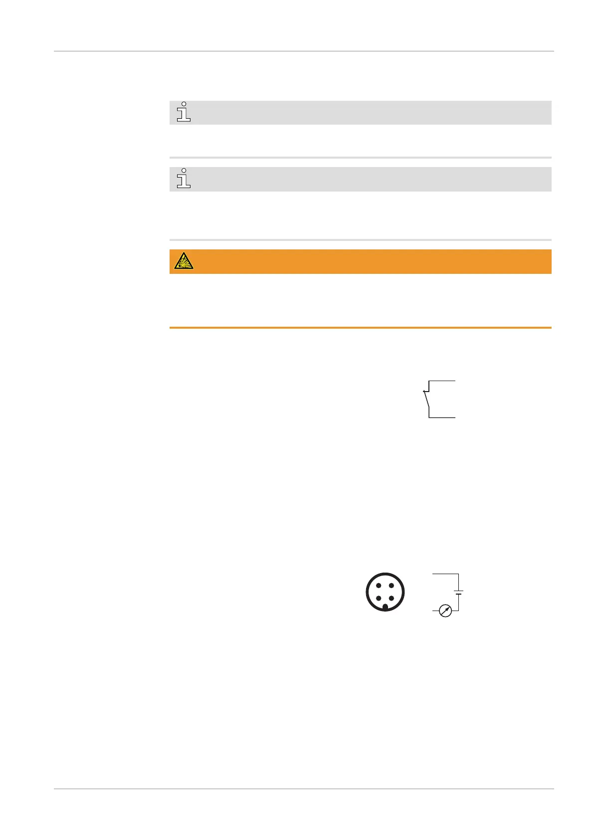
5.7.2 Wiring Diagram Resistance Thermometer
Part no.: 0651563 753 (with transmitter)
Supplier reference: Wika TR31
Connector: M12x1, 4-pin
P&ID position:
TSA+/0101 “gas temp.”
TSA+/0104 “oil temp.” (optional)
1 = Brown ; 3 = Blue
Electrical data:
U
i
=30VDC; I
i
=120mA; P
i
=750mW; L
i
=0µH; C
i
=29.7nF
4 ... 20 mA ► 0 ... 150 °C
Warning signal:
T
warning
(TSA+/0101) = 135°C ► 18.4 mA
T
warning
(TSA+/0104) = see Oil [►34]
Trip signal:
T
trip
(TSA+/0101) = 140°C ► 18.93 mA
T
trip
(TSA+/0104) = see Oil [►34]
 Loading...