5
21
8
11
12
14
5
21
8
11
12
14
5
21
8
11
12
14
5
21
8
11
12
14
5
21
8
11
12
14
Page 9 - Manual FA 01423 -E N - 03/2020 - © CAME S.p.A. -The contents of this manual may be changed, at any time, and without notice. - Translation of the original instructions
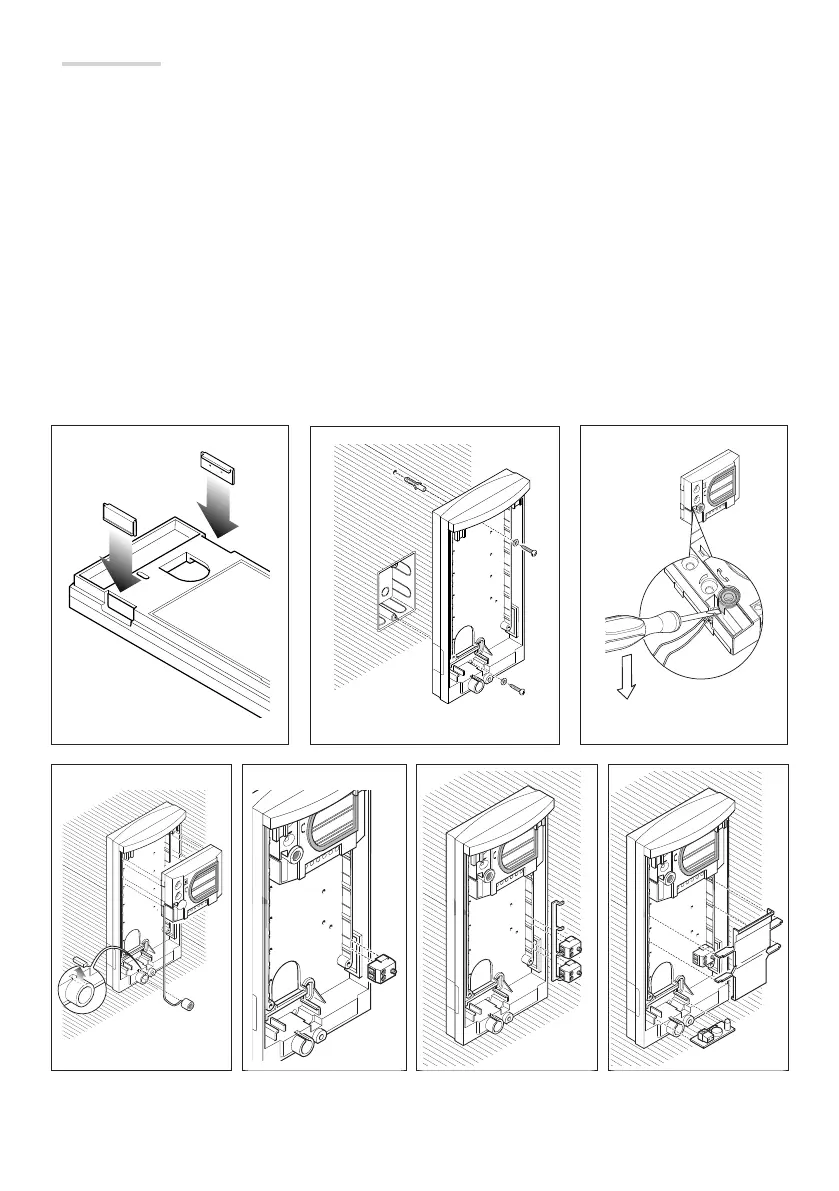
Wall mounting
Fix the two blanking plugs to the base .
Attach the recessed box (with 3 modules or round Ø 65 mm) fl ush with the wall and at a suitable height; fi x the base to the wall
using the screws and expansion plugs provided .
In systems where the Larsen e ect might occur, the microphone can be mounted remotely .
To remove the microphone from its housing, pry it o its base using a small screwdriver, taking care not to damage the
cabling .
Before inserting the microphone into the bottom of the back-box, use pliers to remove the part that is highlighted .
Insert the audio group high up, near to the top of the base .
Fit the microcontact (bottom right) into the correct housing . The front plate is equipped with a common call for the micro-
contacts, to be used when other buttons are to be installed (maximum of 4) .
Insert the lighting group in the relevant housing .
Make the connections and secure the cables using the cable holder .
The cable holder must be located near to the audio group.
 Loading...