Page 4 - Manual FA01357-EN - 07/2019 - © CAME S.p.A. - The contents of this manual may be changed, at any time, and without notice. - Translation of the original instructions
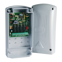
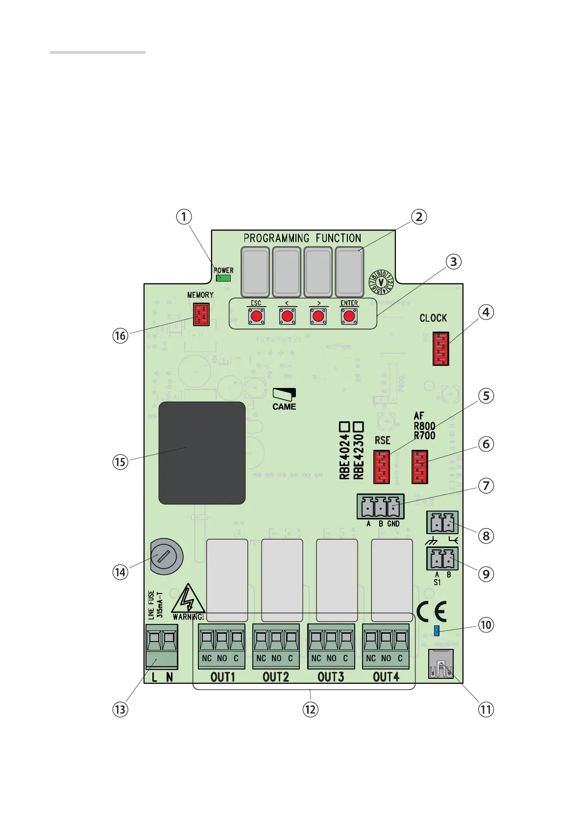
Board description
1. Power-on LED
2. Programming display
3. Programming Buttons
4. SIPA06 CLOCK control-card connector
5. RSE card connector
6. AF/R700/R800 card connector
7. CRP connection terminals
8. Antenna connection terminals
9. keypad/transponder connector terminals
10. USB connection LED
11. Mini USB connector
12. Terminals for connecting devices to govern
13. Control board power-supply terminals
14. Fuse case
15. Transformer (only RBE4230)
16. Memory Roll card connector
Page 4 - Manual FA01357-EN - 07/2019 - © CAME S.p.A. - The contents of this manual may be changed, at any time, and without notice. - Original instructions
 Loading...