5
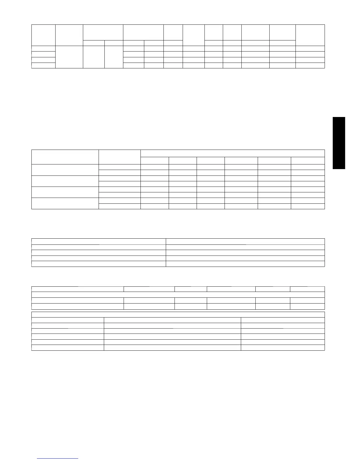
ELECTRICAL DATA
UNIT
S I Z E ---
SERIES
V/PH
OPER VOLTS* COMPR FAN
MCA
MIN
WIRE
SIZE{
MIN
WIRE
SIZE{
MAX
LENGTH
ft. (m)}
MAX
LENGTH
ft. (m)}
MAX
FUSE** or
CKT BRK
AMPS
MAX MIN LRA RLA FLA 60 C 75 C 60 C 75 C
24--- 31
208---230/1 253 197
58.3 11.1 0.6 14.5 14 14 54 (16.6) 52 (15.7) 20
36--- 31 83.0 15.3 0.7 19.8 12 12 63 (19.2) 60 (18.3) 35
48--- 31 104.0 21.2 1.3 27.8 10 10 72 ( 21.9) 68 (20.8) 40
60--- 30 118.0 23.0 1.3 30.1 8 10 93 (28.3) 57 (17.4) 50
* Permissible limits of the voltage range at which the unit will operate satisfactorily
{ If wire is applied at ambient greater than 30_C, consult table 310---16 of the NEC (NFPA 70). The ampacity of non ---metallic---sheathed cable (NM), trade
name ROMEX, shall be that of 60_C conditions, per the NEC (NFPA 70) Article 336---26. If other th a n un coated (no ---plated), 60 or 75_C insulation, copper
wire (solid wire for 10 AWG or smaller, stranded wire for larger than 10 AWG) is u sed, consult applicable tables of the NEC (NFPA 70).
} Length shown is as measured one way along wire path between unit and service panel for voltage drop not to exceed 2%.
* * T i m e --- D e l a y f u s e .
FLA --- F u l l L o a d A m p s
LRA --- L o c k e d R o t o r A m p s
MCA --- Minimum Circuit Amps
RLA ---RatedLoadAmps
NOTE: Control circuit is 24---V on all units and requires external power source. Copper wire must be used from service disconnect to unit.
All motors/compressors contain internal overload protection.
Complies with 2010 requirements of ASHRAE S tandards 90.1
A--WEIGHTED SOUND POWER LEVEL
UNIT SIZE --- VOLT AGE,SERIES
STANDARD
RATING
(dBA)
TYPICAL OCTAVE BAND SPECTRUM (dBA, without tone adjustment)
125 250 500 1000 4000 8000
24--- 31
7 3 --- H i g h S t a g e 49.0 58.0 66.5 69.5 61.0 57.5
7 4 --- L o w S t a g e 52.0 59.5 67.0 69.5 61.0 55.0
36--- 31
7 4 --- H i g h S t a g e 53.5 61.5 68.0 71.0 62.5 57.5
7 3 --- L o w S t a g e 54.0 61.5 67.5 68.0 63.0 56.0
48--- 31
7 4 --- H i g h S t a g e 54.5 59.5 67.0 68.0 60.0 53.5
7 2 --- L o w S t a g e 55.5 61.5 67.0 66.0 60.5 55.0
60--- 30
7 4 --- l o w st a g e 51.4 58.4 63.3 62.5 57.0 50.9
7 4 --- h i g h st a g e 52.4 62.4 62.3 65.5 58.0 51.9
NOTE: Tested in accordance with AHRI Standard 270 ---08. (Not l isted with AHRI).
CHARGING SUBCOOLING (TXV--TYPE EXPANSION DEVICE)
UNIT SIZE --- VOLT AGE, SERIES REQUIRED SUBCOOLING _F(_C)
24--- 31 10 (5.6)
36--- 31 14 (7.8)
48--- 31 13 (7.2)
60--- 30 10 (5.6)
THERMOSTATS
PART NUMBER PROGRAM GAS ELECTRIC HEAT COOL
Performance
T P --- PA C 0 1 7 --- D a y
√ √
1 1
T P --- N A C 0 1 NP
√ √
1 1
THERMOSTAT ACCESSORIES
PART NUMBER BRIEF DESCRIPTION THERMOSTATS USED WITH
SYSTXCCRRS01 Indoor Remote Room Temperatur e Sensor A l l T P --- t h e r m o s t a t s
T P --- E X P 0 1 --- A ExP Computer Programming Accessory TP---P thermostats
TSTATXXCNV10‡ Thermostat Conversion Kit (4 to 5 wire) --- 10 pack All Carrier branded thermostats
T X --- L B P 0 1 LargeDecorativeBackplate T P --- P x x , T P --- N x x , T C --- P x x
TSTATXXSEN01---B* Outdoor Air Temperature Sensor Al l T P --- t h e r m o s t a t s
24ACB7
 Loading...