3
Table 1 – Accessory Usage
Accessory
REQUIRED FOR LOW–AMBIENT
COOLING APPLICATIONS
(Below 555F / 12.85C)
REQUIRED FOR
LONG LINE APPLICATIONS*
REQUIRED FOR
SEA COAST APPLICATIONS
(Within 2 miles / 3.22 km)
Accumulator Standard Standard Standard
Ball Bearing Fan Motor Ye s{ No No
Compressor Start Assist Capacitor and
Relay
Ye s Ye s No
Crankcase Heater Ye s
Ye s
No
Evaporator Freeze Thermostat Ye s No No
Hard Shutoff TXV Ye s Ye s No
Isolation Relay Ye s No No
Liquid Line Solenoid Valve No See Long–Line Application Guideline No
Motor Master[ Control or
Low Ambient Switch
Ye s No No
Support Feet Recommended No Recommended
* For tubing line sets between 80 and 200 ft. (24.38 and 60.96 m) and/or 20 ft. (6.09 m) vertical differential, refer to Residential Piping and Longline Guideline. .
{ Additional requirement for Low–Ambient Controller (full modulation feature) MotorMasterr Control.
Make Piping Connections
!
WARNING
PERSONAL INJURY AND ENVIRONMENTAL
HAZARD
Failure to follow this warning could result in personal injury
or death.
Relieve pressure and recover all refrigerant before system
repair or final unit disposal.
Use all service ports and open all flow–control devices,
including solenoid valves.
CAUTION
!
UNIT DAMAGE HAZARD
Failure to follow this caution may result in equipment damage
or improper operation.
If ANY refrigerant tubing is buried, provide a 6–in (152.4
mm). vertical rise at service valve. Refrigerant tubing lengths
up to 36–in (914.4 mm). may be buried without further special
consideration. Do not bury lines longer than 36 in (914.4 mm).
Outdoor units may be connected to indoor section using accessory
tubing package or field–supplied refrigerant grade tubing of correct
size and condition. For tubing requirements beyond 80 ft,
substantial capacity and performance losses can occur. Following
the recommendations in the Residential Piping and Long Line
Guideline will reduce these losses. Refer to Table 1 for accessory
requirements. Refer to Table 2 for field tubing diameters.
There are no buried–line applications greater than 36 in. (914.4
mm)
If refrigerant tubes or indoor coil are exposed to atmosphere, they
must be evacuated to 500 microns to eliminate contamination and
moisture in the system.
Outdoor Unit Connected To Factory Approved Indoor
Unit
Outdoor unit contains approximate system refrigerant charge for
operation with approved AHRI rated indoor unit when connected
by 15 ft (4.57 m) of field–supplied or factory–accessory tubing,
and factory supplied filter drier. Some indoor units require
additional subcooling to achieve optimal heating performance.
Using Table 5 or 6 – Additional Subcooling Required, check
refrigerant charge for maximum efficiency
Service Valves
Service valves are closed and plugged from the factory. Outdoor
units are shipped with a refrigerant charge sealed in the unit. Leave
the service valves closed until all other refrigerant system work is
complete or the charge will be lost. Leave the plugs in place until
line set tubing is ready to be inserted.
Heat pumps require a piston metering device in the liquid service
valve for proper heating operation. Piston is shipped in the piston
body of the liquid service valve, temporarily held in place with a
plastic cap. Do not remove the plastic cap until line set tubing is
ready to be installed.
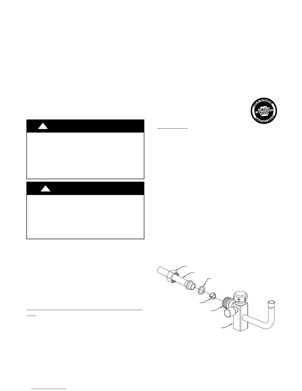
Refer to Fig. 4 and follow these steps for piston installation:
1. Remove plastic cap holding piston in piston body of liquid
service valve.
2. Check that piston size (stamped on side of piston) matches
with number listed on unit rating plate. Return piston to
piston body of liquid service valve (either direction).
3. Find plastic bag taped to unit containing copper adapter
tube, brass nut, and plastic washer.
4. Install plastic washer in the seat inside piston body.
5. Fit brass nut onto adapter tube and install tube onto liquid
service valve. Tighten nut finger tight, then wrench
additional ½ turn only [15−ft lbs (20.3 N−m)]. Over
tightening may damage the plastic washer and service
valve’s piston body.
PISTON BODY
LIQUID SERVICE VALVE
PISTON
PLASTIC WASHER
ADAPTER TUBE
BRASS NUT
A14235
Fig. 4 – Liquid Service Valve with Heating Piston and
Adapter Tube
 Loading...