6
Table 3 – 3–Phase Monitor LED Indicators
LED STATUS
OFF No call for compressor operation
FLASHING Reversed phase
ON Normal
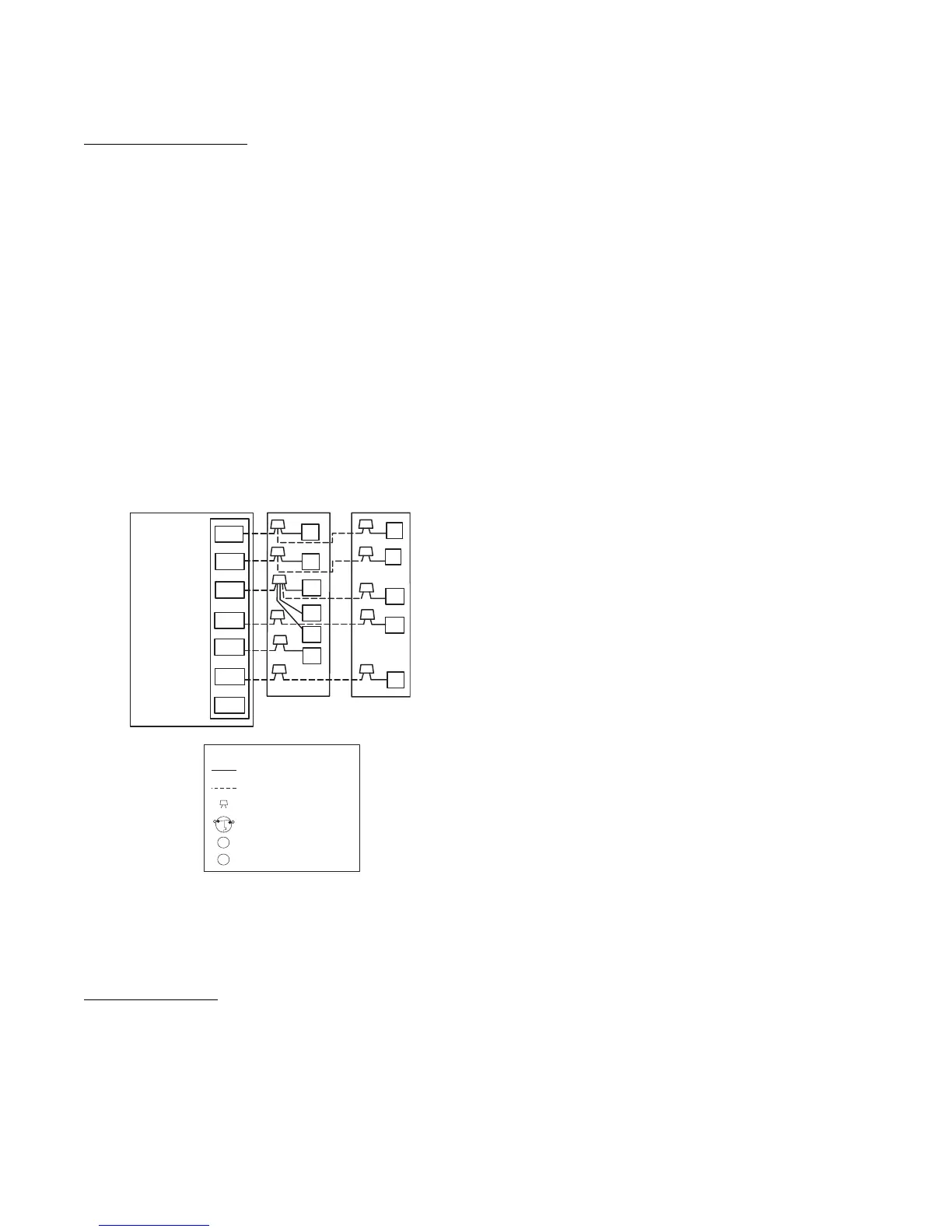
Connect Control Wiring
Route 24v control wires through control wiring grommet and
connect leads to control wiring. See Thermostat Installation
Instructions for wiring specific unit combinations. (See Fig. 11.)
Use No. 18 AWG color–coded, insulated (35°C minimum) wire. If
thermostat is located more than 100 ft (30.5 m) from unit, as
measured along the control voltage wires, use No. 16 AWG
color–coded wire to avoid excessive voltage drop.
All wiring must be NEC Class 2 and must be separated from
incoming power leads.
Use furnace transformer, fan coil transformer, or accessory
transformer for control power, 24v/40va minimum.
NOTE: Use of available 24v accessories may exceed the
minimum 40va power requirement. Determine total transformer
loading and increase the transformer capacity or split the load with
an accessory transformer as required.
24 VAC HOT
R
C
W2
Y
G
R
C
RVS COOLING
C
W2
HP THERMOSTAT
TYPICAL
FAN COIL
HEAT
PUMP
G
O
E
W2
E
W3
R
Y
24 VAC COM
HEAT STAGE 2
COOL/HEAT
STAGE 1
INDOOR FAN
EMERGENCY
HEAT
O
*
*
*
IF AVAILABLE
*
LEGEND
24-V FACTORY WIRING
24-V FIELD WIRING
FIELD SPLICE CONNECTION
OUTDOOR THERMOSTAT
EMERGENCY HEAT RELAY
SUPPLEMENTAL HEAT RELAY
SHR
EHR
ODT
A02325 / A97413
Fig. 11 – Generic Wiring Diagrams
(See thermostat Installation Instructions
for specific unit combinations)
Final Wiring Check
IMPORTANT: Check factory wiring and field wire connections
to ensure terminations are secured properly. Check wire routing to
ensure wires are not in contact with tubing, sheet metal, etc.
Compressor Crankcase Heater
When equipped with a crankcase heater, furnish power to heater a
minimum of 24 hr before starting unit. To furnish power to heater
only, set thermostat to OFF and close electrical disconnect to
outdoor unit.
A crankcase heater is required if refrigerant tubing is longer than
80 ft (23.4 m), or when outdoor unit is 20 ft (6.09 m) below indoor
unit. Refer to the Residential Piping and Long Line Guideline.
Install Electrical Accessories
Refer to the individual instructions packaged with kits or
accessories when installing.
 Loading...