8 30AWH
Electrical connections (Fig. 17)
WARNING
Make water connections before electrical connections.
Make ground connection prior to any other electrical connections
All eld electrical connections are the responsibility of the installer.
4XJUDI$POOFDUJPO4FFöH
S1: O/ON
S2: Cooling/Heating
S3: Normal / Economic
"VYJMJBSZDPOOFDUJPOTTFFöH
1=3 Way valve
"MBSNEFGSPTU%FIVNJEJöFS
3=Trace Heater / Additional Water pump
4=External heat source / Defrost
5=Alarm / Ambient temperature reached
6=Limitation frequency
7=Sanitary Input
8=Alarm Input
9=External temperature probe (NTC 3k@25°C)
10=External water pump
Note:
The quality of the contacts must be greater than 25mA @ 12V
Remove the front panel, the electric parts appear at the
front side.
The power supply cables can be inserted into the pipe
IPMFT#FTVSFUPöYUIFQPXFSDBCMFXJUICVOEMJOHCBOE
sold on the market so that they do not make contact with
the compressor and the hot pipes.
To ensure good tensile strength, the electric cables must be
fastened using the cable-holder on the plate.
(Only for size 015 use the strain relief supplied with the unit)
The unit can be controlled and set via:
User Comfort Interface wire control 33AW-CS1 (Optional)t
Wire remote control 33AW-RC1 (Optional)t
Switches (not supplied)t
For the electrical connections refer to Figure 17, while, for
use, refer to the relative manuals.
Wired control For installation of wired remote controller please refer to the control installation manual.
1PXFSTVQQMZ
Size the cable, the cables must be H07 RN-F type (3x2,5 mm
2
).
According to the installation instructions, all devices for disconnection from the power supply
mains must have a contact opening (4 mm) to allow total disconnection according to the conditions
provided for the overvoltage class III.
To prevent any risk, the power cable must only be replaced by the technicians of the after-sales
service.
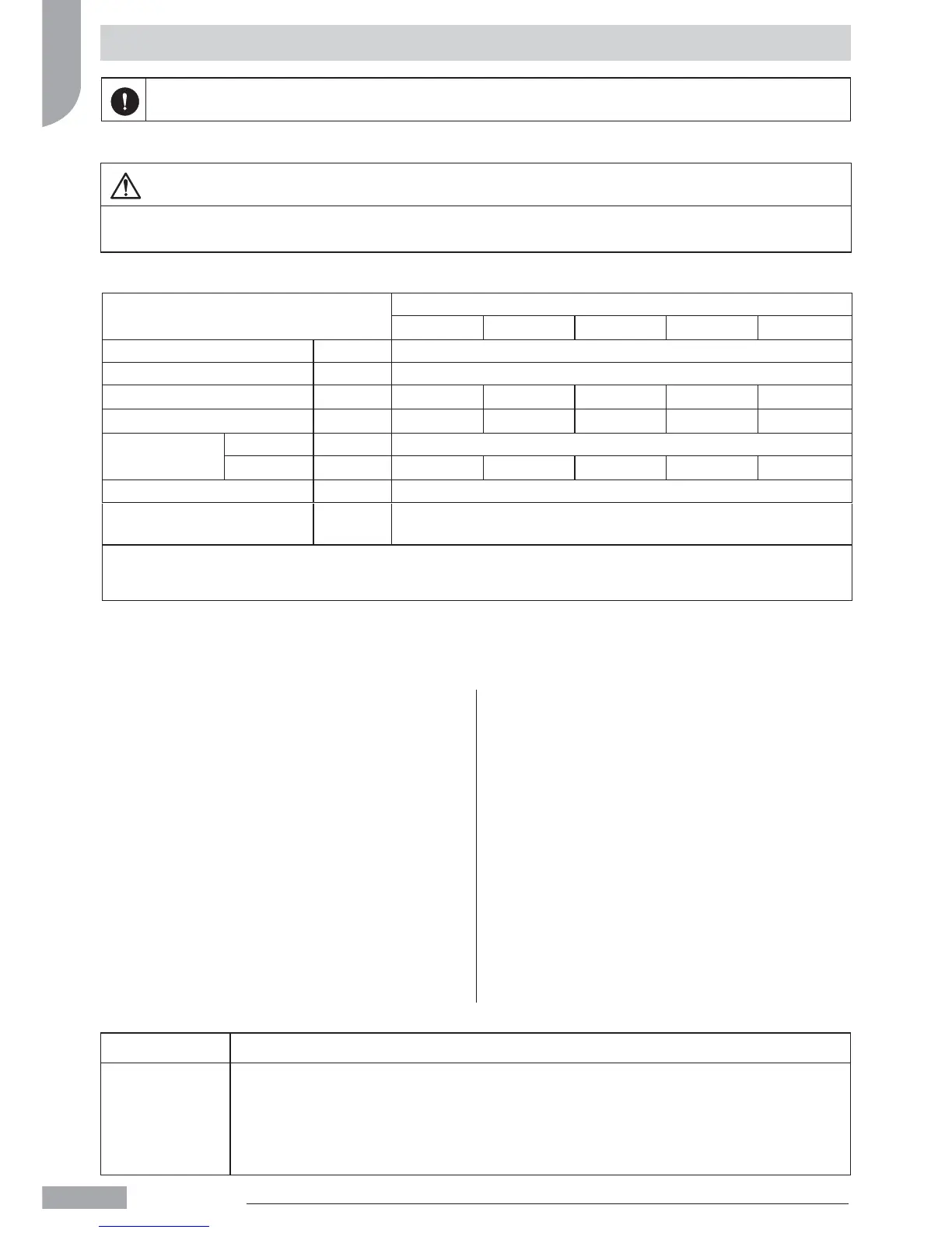
Also check the supply voltage and frequency of the indoor unit.
Unità
30AWH
004_ 006_ 008_ 012_
015_
1PXFSTVQQMZ V- ph - Hz 230 - 1 -50
Allowable Voltage Range V 207 ÷ 254.
Maximum power drawn kW 2 2,3 2,7 5,1
5,1
Maximum current drawn A 7,2 11 14 23
20
1PXFS
Fuses
Type gL Type
Current A 10 - Type B 15 - Type B 15 - Type B 25 - Type D
25 - Type D
1PXFSTVQQMZDBCMFT mm H07RN-F 3 x 2.5mm
.BYJNVN1VNQ$VSSFOU
External circulation
A2
Use cables H03VV-F 4x0.75 mm to connect the control to wire NUI (33AW-CS1)
and H03VV-F 6x0.75 mm to connect the control to wire SUI (33AW-RC1)
English
 Loading...