Capacity Control System consists of a multiple-step
water temperature controller, electric cylinder bank
unloader(s) and liquid line solenoid
valve.
A hot gas
bypass arrangement on the final step of unloading is
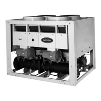
factory supplied for models 30GT020 60 Hz and 30GT0 15
50 Hz. Factory-installed stubs are provided to facilitate
field installation of hot gas bypass for all other units.
MULTIPLE-STEP CONTROLLER consists of load
switches actuated by pressures developed
ina
temperature-
sensing bulb located in the nozzle of the return water
line of the chilled water system.
To remove the sensing bulb, loosen the setscrew at the
top of well and pull the bulb out. Before replacing the
bulb, half fill the well with heat conductive compuund
(multi-service grease for high or low humiditv conditions
can be used). Then insert the bulb entirely
ihto
the well
and tighten the setscrew. Be sure
rhe
spEir
collar is in the
well recess.
The controller is factory set to control from return
water temperature through a cooling range of IO F
(5.6C). The sequence switches are factory calibrated and
sealed and should not require any field changes. Table 5
shows the
factury-set
temperature steps for the 2- and
3-step controllers.
The return water temperature: at
whict-t
the last step of
capacity unloads is indicated by the leaving water tem-
perature design set point on the adjustable dial (Fig. 12).
Example: design set point is at 44 F (6.7 C). On
a
reduc-
tion in load, the capacity of the unit is reduced to zero
when return water temperature drops to 44 F
(6-7
C).
Any alteration of factory settings, except design set
point, without Carrier authorization, may void
Carrier Warranty.
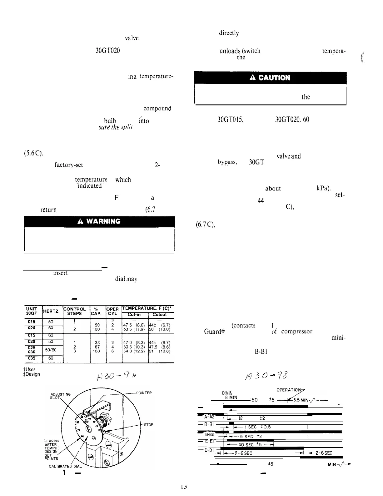
Design Set Point Adjustment
-
When unit is ready for
operation. msert small screwdriver in adjusting slot
(Fig. 12) and rotate to turn diaf (the dialmay be turned by
hand if desired).
fable 5
-
Capacity Control Steps
*Return chilled water temperature.
tUses hot gas bypass.
SDesign
set point.
Rotate until the design set point for the installation
appears directIy under the pointer. Insert a thermometer
in the return chilled water connection and allow the unit
to run through a cycle. At the instant the last step of
capacity unloads
{switch
no. 1 opens), read the tempera-
ture. If it is not the same as the dial reading, the variation
can be compensated by shifting the control point slightly.
k’
c;
%.
I
Do not force the dial past the stop. This could cause
loss of the control point and damage the instrument.
HOT GAS BYPASS VALVE is factory-installed on
Models 30CITOl5, 50 Hz and 30GT020.60 Hz. It modu-
lates flow of hot gas into refrigerant circuit in response to
variations from preset suction pressure. A sudden de-
crease in suction pressure causes valve to admit more hot
gas to restore the preset pressure level. The hut gas enters
the refrigerant circuit through the connecting tube
between the thermal expansion valveand the cooler. With
hot gas
bypass?
the 3OGT unit operates down to a lower
load condition; the result is less frequent off-on cycling
of the chiller.
The bypass valve is factory set to begin opening when
suction pressure drops to abuut 62 psig (427 kPa). This
pressure corresponds to a chilled water controller
set-
point of approximately 44 F (6.7 C). If the chilled water
set point is lower than 44F (6.7 C), it is necessary to
decrease the bypass valve setting for proper operation.
Conversely, for chilled water set points above 44F
(6.7C), the bypass valve setting must be increased. A
change in condensing temperature also requires a change
in bypass valve set point, As condensing temperature
decreases, decrease the bypass valve ser point until it
opens at desired conditions.
OPERATION
Refer to Control Circuit diagram on the unit, or in the
Wiring Diagrams publication.
Timer Functions (See Fig. 13)
1. Switch A (conracts A-A
I
and A-A2) provides Time
Guard@
function. Start af campressor is delayed
approximately 5.5 minutes after shutoff. The mmi-
mum rime between starts of compressor is 8 minutes.
2. Switch B (contacts
B-B1
and B-B2) starts compressor.
3. Switch D (contacts D-Dl) bypasses the low-pressure
switch (LPS) for 2.5 minutes at start-up for winter
start control.
/q
3
0
‘-
pB
(BLACK DENOTES CLOSED CONTACTS) TIMER POSITION DURING
OMIN Off
UNIT
1
8
MIN
I
150 SEC
%
OPE:zN+
-
A-AI
-
I_
COMPRESSOR STARTS
-
‘L
12
SEC
f2
I
I
-
B-BI ’
-
-
E-El
I
-D-T
-2-6
SEC
4
+2-6SEC
D-02 I
-
150 SEC
+5
----l-5.5
MINQ---
Fig. 13
-
Timer CycleFig.
‘I
2
-
Set Point Adjustment
 Loading...