Sequence of
ContrOt
-
At start-up, with the water
temperature controller (WTC) calling for cooling and all
safety devices satisfied,
the control circuit switch is
closed.
With minimal demand for cooling, only the first
WTC switch is made. The timer motor starts, the liquid
line solenoid valve opens, and condenser fan no. 1 starts.
Fans no. 2 and 3 start if high side pressure is higher than
260 psig (I 793 kPa). After a delay by Time Guard of
12
seconds to approximately 8 minutes depending on the
timer position, the compressor starts, unloaded. As cool-
ing demand increases, unit capacity increases as follows:
UNITS WITH TWO-STEP CONTROLLER
~
The
second WTC switch makes: the compressor loads and the
unit is operating at full capacity.
UNITS WITH THREE-STEP CONTROLLER
-
The
second WTC switch makes: one compressor unloader
is de-energized increasing the capacity.
The third WTC switch makes: the second compressor
unloader is de-energized increasing the unit to full
capacity.
ALL UNITS
-
A pumpout relay (POR) in the control
circuit is energized when WTC no. I switch makes. A set
of normally open POR contacts close, completing a com-
pressor control circuit which bypasses the WTC switches.
As cooling demand is satisfied, WTC switches break
in descending sequence. The LLS valve closes, stopping
the flow of
Liquid
refrigerant to the cooler and subse-
quent suction gas to the compressor. After the last WTC
switch breaks, the compressor continues to run because
of the WTC switch bypass. With no refrigerant returning
to the compressor, low side pumpout takes place and the
compressor shuts down on low-pressure control. The
compressor does not restart until the WTC again calls for
cooling.
HOT GAS BYPASS (factory-installed on 30GT015
50 Hz, and 30GT020 60 Hz).
On the
last
step of capacity control (only WTC switch
no.
B
is closed), the hot gas bypass valve is energized.
This allows unit to operate at a lower
Load
condition
than is provided in the normal function of the WTC, with
Less
frequent on-off cycling of the compressor.
Complete Unit Stoppage
CAUSES
~
Interruption of supplied power, open
control circuit switch (SW), open chilled water flow
switch (CWFS), open contacts in auxihary interlock
(CWPS), open discharge thermostat (DGT) or com-
pressor overtemperature protection (COTP, for 30GT0
15
60 Hz only), open high-pressure switch (HPS), open low
water temperature cutout (LWTC).
RESTART
-
The unit recycles and restarts automati-
cally under Time Guard@ control when power is restored,
or when SW is closed or when contacts in CWFS or
CWPS are closed.
Stoppage by DGT or COTP, HPS or LWTC requires
manual resetting of the control circuit to restart the
Time Guard timer. This is done by opening and closing
the control circuit switch (SW).
After Stoppage by how-Pressure Switch (LPS]
-
If LPS is not closed 2-112 minutes after compressor
starts, the compressor stops and locks out and LPS must
be closed before timer can recycle to restart the
compressor.
If LPS opens anytime during unit operation, com-
pressor stops and timer starts. Compressor restarts
in approximately 5.5 minutes. For 2-l
12
minutes, LPS is
bypassed. If it has not closed by this time, the compressor
stops and locks out. The compressor cannot restart until
LPS is closed.
ff unit or circuit stoppage ‘occurs more than once
due to any safety device, the trouble should be
corrected before any attempt to restart.
Cooler Tubes
-
Plugging and Retubing
-
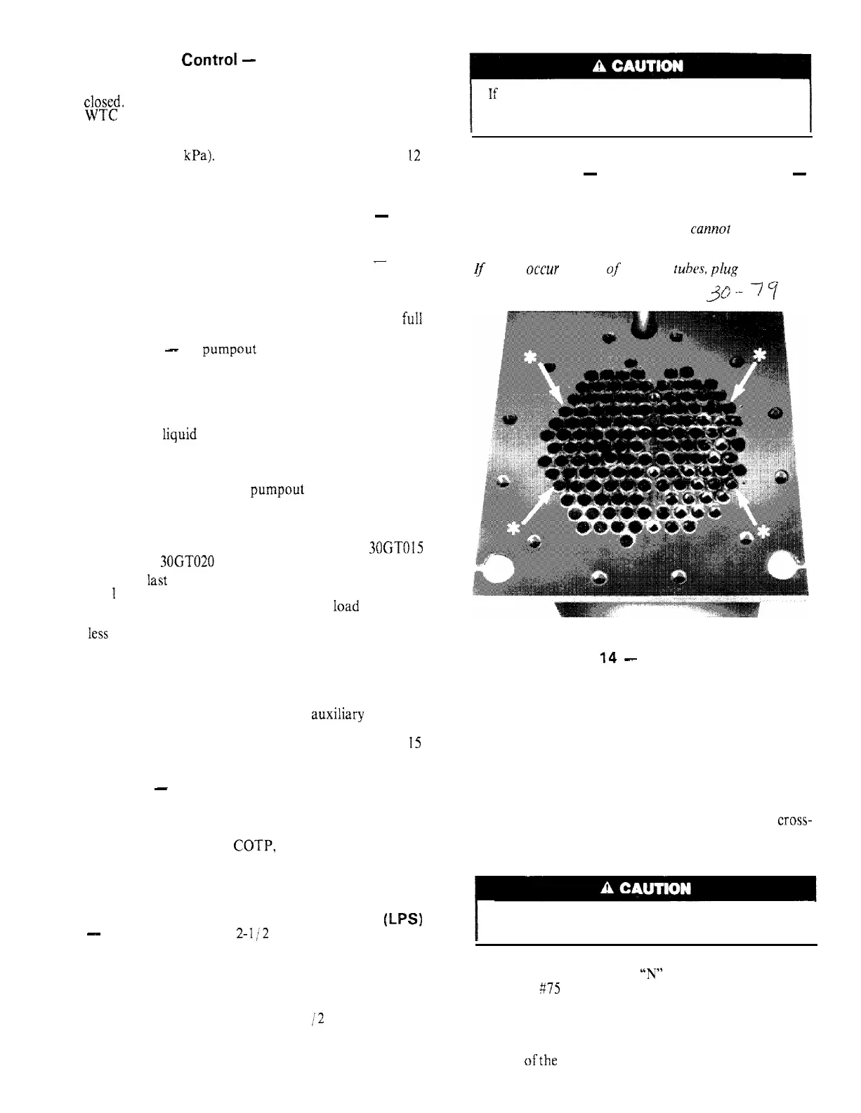
When the cooler heads and partition plates are removed,
the tube sheets are exposed showing the ends of the tubes
as seen in Fig. 14. Four tubes in the bundle are secured
inside the cooler at the baffles and
cannut
be removed.
These are identified on the tube sheets by a drill mark
horizontally adjacent to each of the 4 tubes. See Fig. 14.
iJ’
leaks
occur
in any of these 4
tuh~s,
plug the tube(s)
as described under Tube Plugging.
30--
-77
‘Four fixed tubes (cannot be removed) identified by adjacent
drill points.
Fig.
‘I4
-
Tube Sheet
TUBE PLUGGING -- A leaky tube(s) can be plugged
until retubing can be done. The number of plugged tubes
determines how soon the cooker must be retubed. If
several tubes require plugging, check with your local
Carrier representative to find out how the number and
location will affect unit capacity.
Figure 15 shows an Elliott tube plug and a
cross-
sectional view of a plug in place. Table 6 lists the com-
ponents for plugging.
Use extreme care when installing plugs to prevent
damaging the tube sheet sections between the holes.
I
Clean parts with Locquic “N” and apply a few drops
of Loctite 875 to obtain a tight seal without using too
much force to set the pin.
Usually plugs can be removed by heating the projecting
end of the pin to approximately 1000 F (540 C) and
chilling quickly with water. Apply the heating flame to
the side ofthe pin to prevent overheating the tube sheet.
14
 Loading...