11
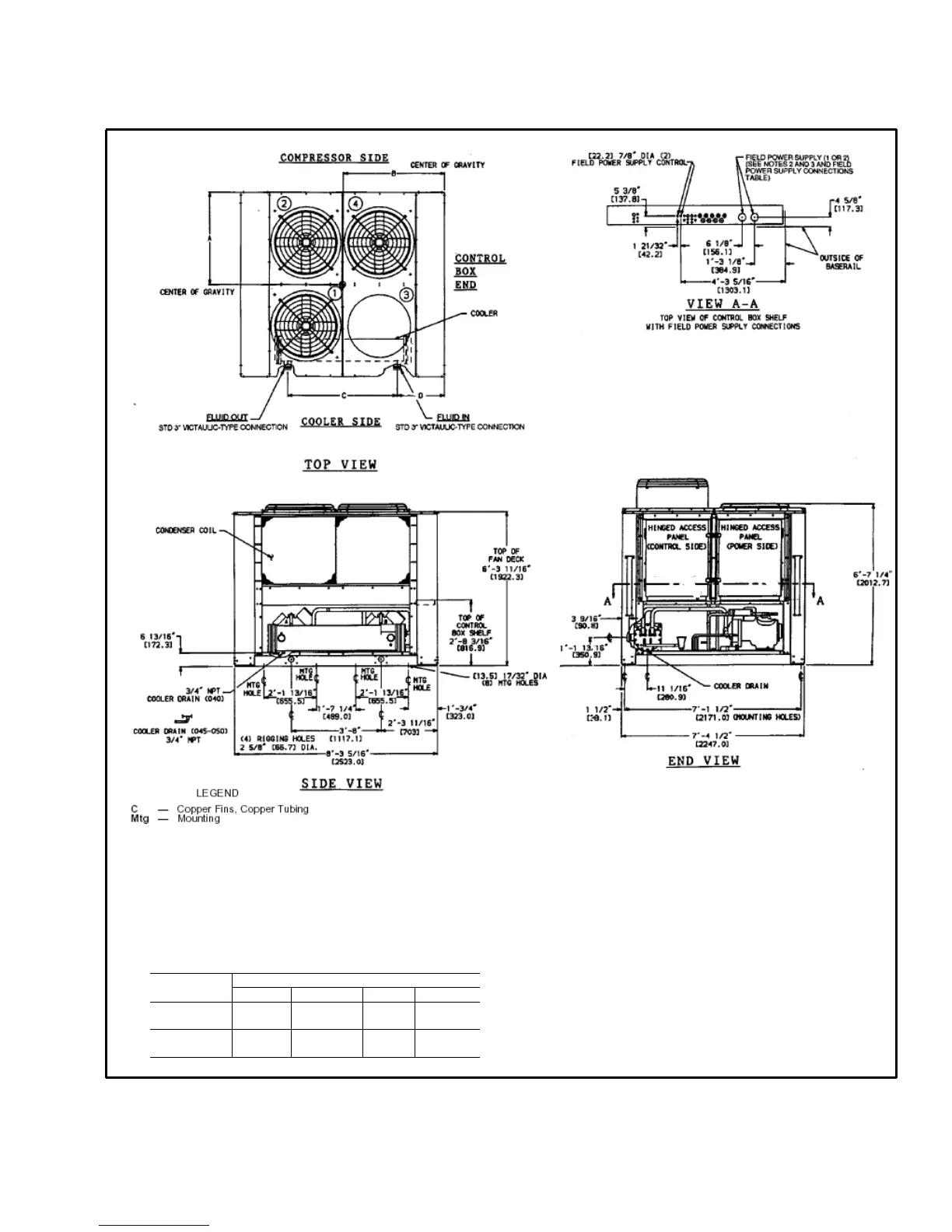
Base unit dimensions — 30GTN,GTR050
NOTES:
1. Unit must have clearances for airflow as follows:
TOP – Do not restrict in any way.
ENDS – [1524] 5 ft
SIDES – [1829] 6 ft
2. Mounting holes may be used to mount unit to concrete pad. They are not
recommended for spring isolator location.
3. If spring isolators are used, a perimeter support channel between the unit
and isolators is recommended.
4. Dimensions in [ ] are millimeters.
UNIT DIMENSIONS
30GTN,GTR “A” “B” “C” “D”
050
3’-5 7/8”
[1064]
3’-11”
[1194]
5’-5 ½”
[1663]
1’-5 3/16”
[436.6]
050C
3’-6”
[1067]
3’-11 3/16”
[1199]
5’-5 ½”
[1663]
1’-5 3/16”
[436.6]
 Loading...