8
1
2
1
1
2287
A
1
1
1000
1000
1830
1830
2
B
2256
30GX-207
30GX-227
30GX-247
30GX-267
30GX-298
30GX-328
30GX-358
2
kg
B mm
A mm
5540
5570
2895
30GX207
30GX227
5996
6134
6365
2470
30GX247
30GX267
6911
7918
8124
1250
30GX328
30GX358
8741
7354
2220
30GX298
7826
2000
1830
2000
1830
20002000
1525
1525
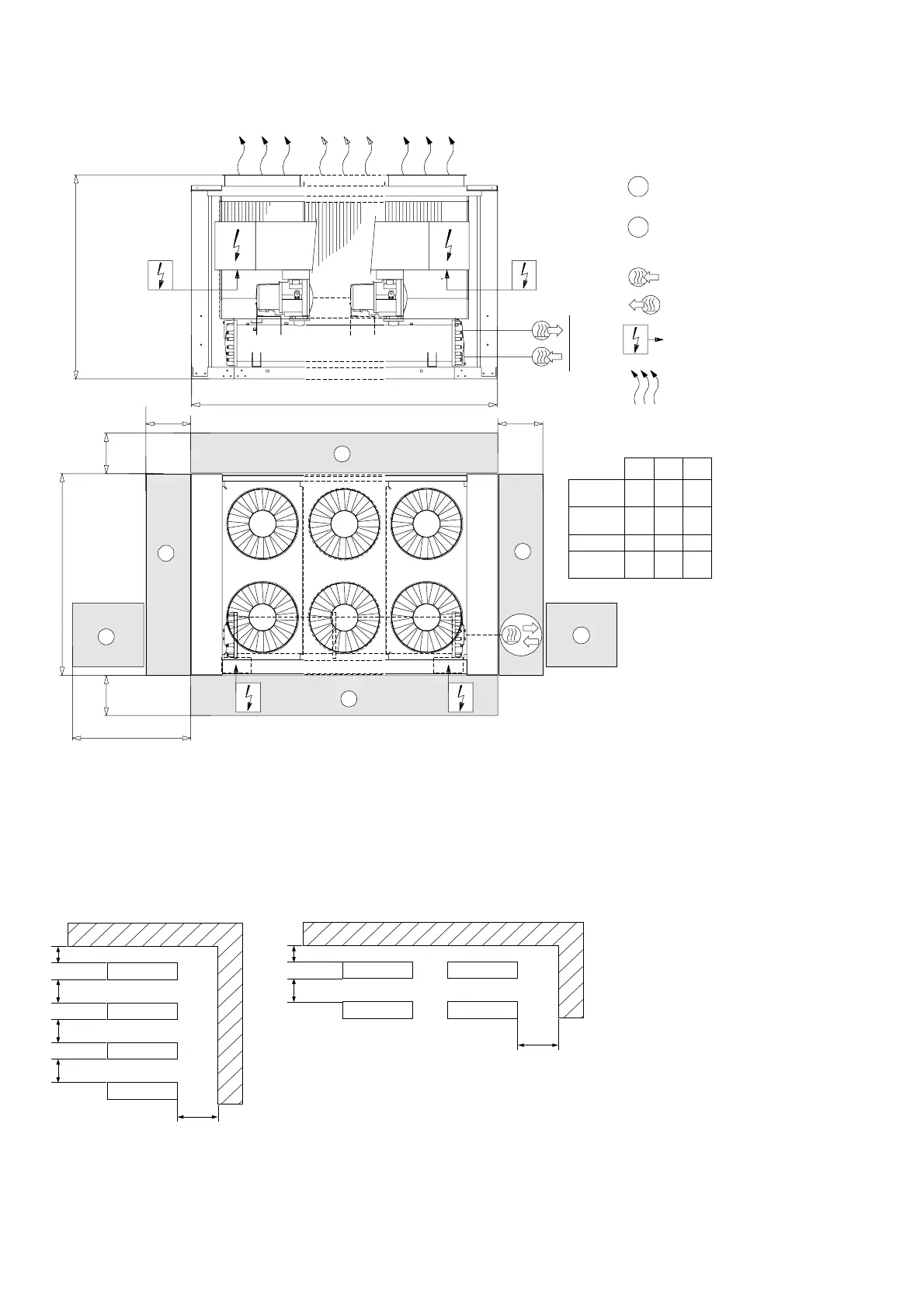
3 - DIMENSIONS, CLEARANCES, WEIGHT DISTRIBUTION (CONT.)
3.4 - 30GX 207-358
NOTE: Refer to the certified dimensional drawings supplied with the unit, when designing an installation.
Multiple chiller installation (see note 2)
SOLID SURFACE AREA SOLID SURFACE AREA
Clearances required for evaporator tube
removal. Clearances can be either on the left
or on the right hand side.
Water inlet
Water outlet
Power supply
kg: total operating weight
Clearances required
for operation and maintenance
Air outlet - do not obstruct
Notes:
1. Unit must have clearances for air flow as follows:
Top: do not restrict in any way
2. In case of multiple chillers (up to four units), the
respective clearance between them should be increased
from 1830 to 2000 mm for the side space requirement.
3. Clearances sre required for cooler tube removal.
 Loading...