53
The other method for reducing flow on a constant speed
pump is impeller trimming. The impellers in the pumps provid-
ed in the 30RB hydronic kit can be easily removed for this
purpose. Refer to the vendor literature packet supplied with the
hydronic package information on Seal Replacement in the
Service Section, and follow instructions for impeller removal
and trimming. Trimming should only be done by a qualified
machine shop that has experience in this operation. Contact
your local Carrier representative for a recommended machine
shop.
Impeller trimming has the added benefit of maximum bhp
(brake horsepower) savings, which can recover the cost
incurred by performing the impeller trimming.
PUMP VFD — Pumps may be ordered with a variable fre-
quency drive (VFD) for speed control.
SENSORLESS CONTROL (CLOSED LOOP) — ACTIVE
SETUP 1 — The VFD provided with the pump from the fac-
tory is configured for sensorless control. Default set points are
entered for the unit according to nominal tonnage of the unit.
Table 8 shows the settings from the factory. For details on op-
erating the drive display, see the pump installation and opera-
tion manual, and for more detailed information on the drive,
see IVS 102 Operating Instructions. These manuals are sup-
plied in the control box of the chiller.
The following set points should be verified or modified for
the actual installation.
Parameter 20-21 Setpoint, Hd, Ft-Wc
Parameter 22-89 Design Flow Setpoint, GPM
Parameter 22-87 Pressure at no-flow speed, Hmin, Ft-Wc
(40% of Hd)
When changing set points, assure values are within the
pump curve for the pump provided with the unit.
Minimum speed for the pump is set at 50 Hz, Parameter
4-12. This may be changed as long as the corresponding flow
rate meets the minimum flow requirement for the chiller.
REMOTE SENSOR (CLOSED LOOP) — ACTIVE
SETUP 2 — The drive may be set up to use a remote sensor
instead of sensorless pump control. For a remote sensor con-
trol change Active Setup on the drive from 1 to 2, Parameter
0-10. The drive will read a 0-10vdc or a 0/4-20 mA signal
from the sensor. Switch S2-01 must be set to Off (default set-
ting) for 0-10 vdc or On for 0/4-20 mA. The switch is located
behind the display. The cover must be removed and the display
will snap off to access this switch.
The set point is defined by Parameter 20-21, Setpoint 1.
This is a percentage of the maximum signal from the sensor.
The default is 80%.
REMOTE CONTROLLER (OPEN LOOP) — ACTIVE
SETUP 3 — Drive may be controlled by external sources. For
a remote control of the drive change Active Setup on the drive
to 3, Parameter 0-10. An input signal can used to control the
drive speed. Input signal may be 0-10 vdc or 0/4-20 mA. The
setup is the same as a remote sensor.
A BACnet card is also included with the drive. For
BACnet, use Setup 3. The communication settings are in sec-
tion 8 of the drive parameters. See drive manual for details.
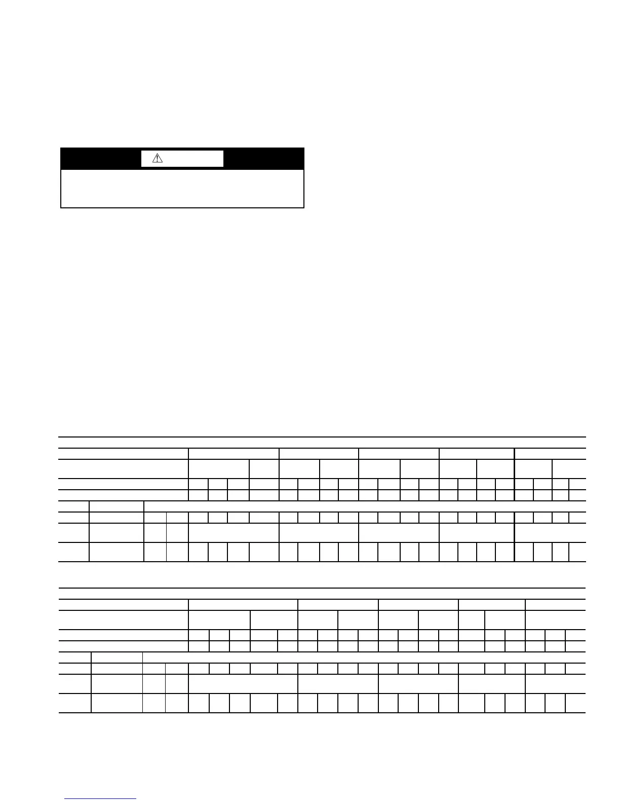
Table 8 — Default Settings for Sensorless Control — Setup 1
CAUTION
After trimming, the impeller MUST be balanced. Failure to
balance trimmed impellers can result in excessive vibra-
tion, noise, and premature bearing failure.
SINGLE PUMP
Unit Size (tons) 60,70 80, 90, 100 110,120,130 150 160, 170, 190
Pump
4380
3x3x8
4380
3x3x6
4380
3x3x8
4380
3x3x6
4380
3x3x8
4380
3x3x6
4380
4x4x8
4380
4x4x6
4380
4x4x8
4380
4x4x6
HP 3 5 7.5 10 5 7.5 10 15 5 7.5 10 15 5 7.5 10 15 5 7.5 10 15
Impeller Dia (inches) 6.5 7.3 8.15 5.4 7.3 8.15 5.4 6.1 7.3 8.15 5.4 6.1 6.5 7.4 4.6 5.2 6.5 7.4 4.6 5.2
Param. Desc.
20-21 Setpoint 1 Hd ft wc 30 45 55 95 40 50 90 120 35 45 80 115 25 50 70 95 25 45 65 90
22-89
Flow at
Design Point
gpm 150 200 270 340 410
22-87
Press at No
Flow Speed
40%
Hd
ft wc 12 18 22 38 16 20 36 48 14 18 32 46 10 20 28 38 10 18 26 36
DUAL PUMP
Unit Size (tons) 60,70 80, 90, 100 110, 120, 130 150 160, 170, 190
Pump
4382
4x4x8
4382
3x3x6
4382
4x4x8
4382
4x4x6
4382
4x4x8
4382
4x4x6
4382
4x4x6
4382
6x6x6
4382
4x4x6
HP 3 5 7.5 7.5 10 5 7.5 10 15 5 7.5 10 15 7.5 10 15 7.5 10 15
Impeller Dia (inches) 6.5 7.3 8.15 5.25 5.9 7.3 8.15 5.4 6.0 7.3 8.15 5.4 6.0 5.0 4.6 5.2 5.0 4.6 5.2
Param. Desc.
20-21 Setpoint 1 Hd ft wc 30 45 55 75 95 40 50 90 120 35 45 80 115 50 70 95 45 65 90
22-89
Flow at
Design Point
gpm 150 200 270 340 410
22-87
Press at No
Flow Speed
40%
Hd
ft wc 12 18 22 30 38 16 20 36 48 14 18 32 46 20 28 38 18 26 36
 Loading...