EasyManuals Logo

Carrier 30RB060-390 User Manual

Carrier 30RB060-390
76 pages
To Next Page IconTo Next Page
To Previous Page IconTo Previous Page
Page #61 background imageLoading...
Page #61 background image
61
(–)
(+)
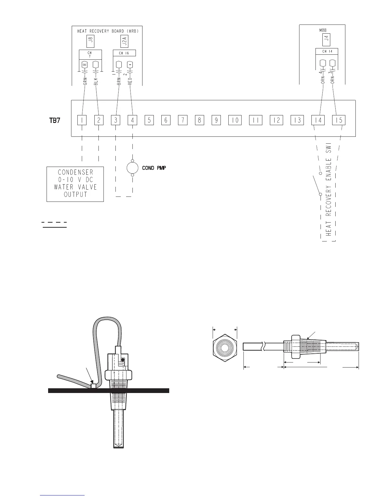
Fig. 59 — Optional Heat Reclaim Control Typical Field Wiring
NOTES:
1. Terminals 1 and 2 of TB7 are for external connection of heat
reclaim condenser water valve.
2. Terminals 3 and 4 of TB7 are for external connection of field-
supplied heat reclaim water pump control relay.
3. The maximum load allowed for the condenser pump relay is
5 va sealed, 10 va inrush at 24 v.
4. Terminals 14 and 15 of TB7 are for external connection of
heat reclaim remote enable switch.
5. Terminals 5 through 13 of TB7 are for the connection of
factory-installed solenoid valve control wiring.
LEGEND
Field Control Wiring
Factory-Installed Wiring
a30-4742
WIRE TIE
LOOP
THERMISTOR WIRE
AND SECURE
TO CHILLED WATER PIPE
INSERT THERMISTOR UNTIL
O-RING MEETS THE
THERMISTOR WELL BODY.
Fig. 60 — Dual Leaving Water Thermistor
(Part No. 30RB660036)
5/8 in. HEX
6" MINIMUM
CLEARANCE FOR
THERMISTOR
REMOVAL
1.188 in.
2.315 in.
1/4-18 NPT
Fig. 61 — Dual Leaving Water Thermistor Well
(Part No. 00PPG000008000A)

Questions and Answers:

Question and Answer IconNeed help?

Do you have a question about the Carrier 30RB060-390 and is the answer not in the manual?

Carrier 30RB060-390 Specifications

General IconGeneral
BrandCarrier
Model30RB060-390
CategoryChiller
LanguageEnglish

Related product manuals