26
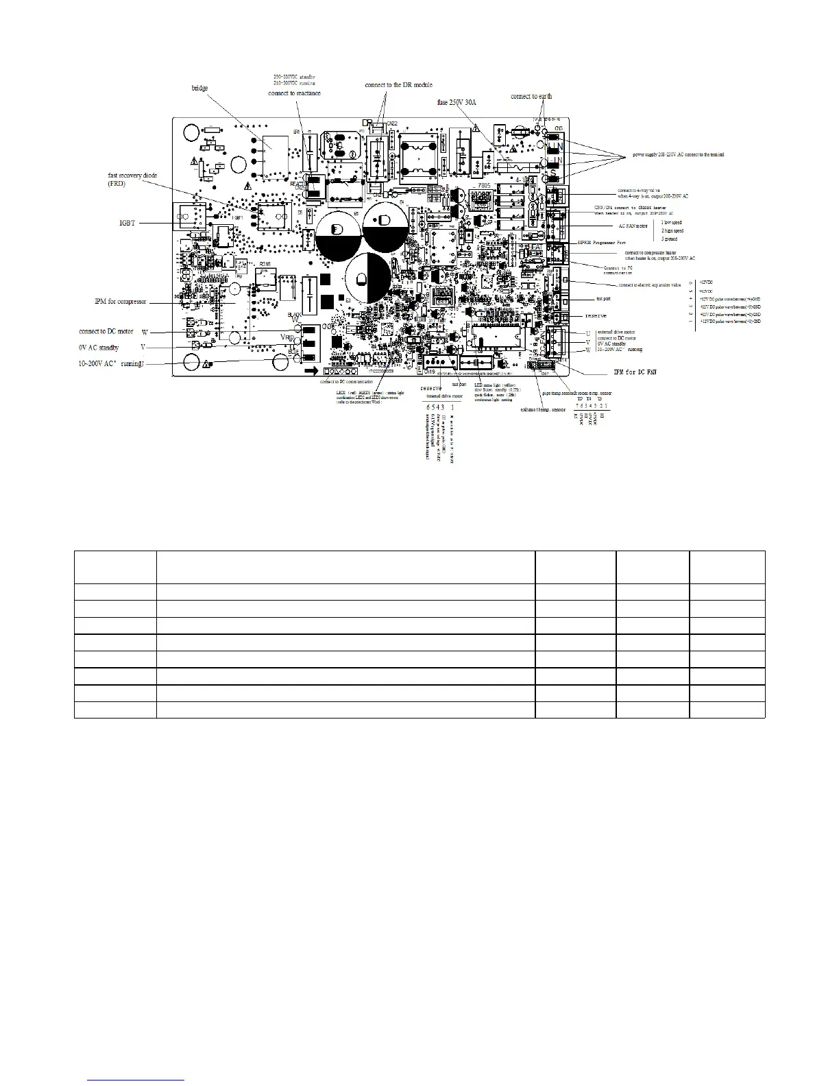
PCB DIAGRAMS (CONT)
Fig. 29 – Sizes 18−24 208−230V
NOTE: After power on, LED3(Green color) and LED2(Red color) will flash if the unit has some problems.
Table 17—LED Codes
No. Problems
LED3
(Green)
LED2
(Red)
IU display
1 standby for normal O X
2 Operation normally X O
3 IPM malfunction or IGBT over-strong current protection ☆ X P0
4 Over voltage or too low voltage protection O O P1
5 EEPROM parameter error O ☆ E5
6 Inverter compressor drive error X ☆ P4
7 Inverter compressor drive error ☆ O P4
8 Inverter compressor drive error ☆ ☆ P4
O(light) X(off) ☆(2.5Hz flash)
 Loading...