32
DIAGNOSIS AND SOLUTION (CONT)
Index 1
1 Indoor or Outdoor DC Fan Motor (control chip is in fan motor)
S Power on and when the unit is in standby, measure the voltage of pin1−pin3, pin4−pin3 in fan motor connector. If the voltage value
is not in the range shown in Table 18 or Table 19, the PCB has an issue and needs to be replaced.
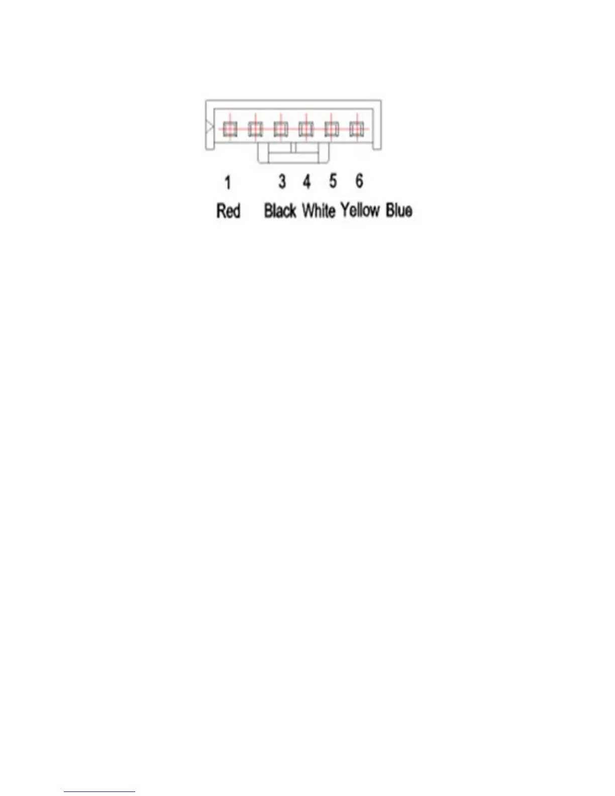
Fig. 34 – Motor Connector
Table 18—DC motor voltage input and output (voltage: 220−240V~)
NO. COLOR SIGNAL VOLTAGE
1 Red Vs/Vm 280V~380V
2 --- --- ---
3 Black GND 0V
4 White Vcc 14-17.5V
5 Yellow Vsp 0~5.6V
6 Blue FG 14-17.5V
Table 19—DC motor voltage input and output (voltage : 115V~)
NO. COLOR SIGNAL VOLTAGE
1 Red Vs/Vm 140V~190V
2 --- --- ---
3 Black GND 0V
4 White Vcc 14-17.5V
5 Yellow Vsp 0~5.6V
6 Blue FG 14-17.5V
2 . Outdoor DC Fan Motor (control chip is in the outdoor PCB)
S Power on the unit and check if the fan runs normally. If the fan runs normally, the PCB has an issue and needs to be replaced. If the
fan does not run normally, measure the resistance of each two pins. If the resistance is not equal to each other, the fan motor has an
issue and needs to be replaced, otherwise the PCB has an issue and needs to be replaced.
3 Indoor AC Fan Motor
S Power on the unit and set the unit in FAN mode at the high fan speed. Run for 15 seconds then measure the voltage of pin1 and
pin2. If the voltage value is less than 100V(208~240V power supply) or 50V(115V power supply), the PCB has an issue and needs
to be replaced.
 Loading...