sequencer heaters KFAEH2501N09, KFAEH2601F15,
KFAEH2801C15, KFAEH1001F24, KFAEH1101F30; or
relay heaters KFCEH1401N09, KFCEH1501F15,
KFCEH1701C15, KFCEH1801F20, KFCEH1901C20,
KFCEH2101F24, KFCEH2201F30.
NOTE: Relay heaters are suggested to maximize comfort during
defrost.
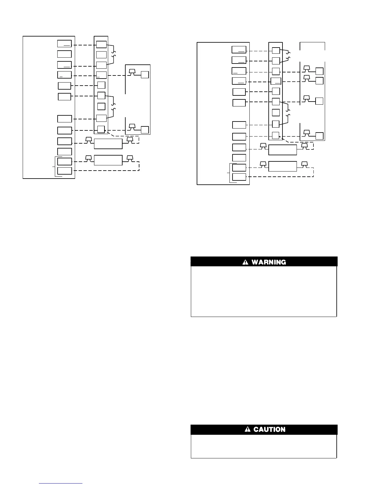
Complete system low-voltage wiring as shown in Fig. 9, 10, 11,
and 12.
NOTE: Where local codes require thermostat wiring be routed
through conduit or raceways, splices can be made inside the fan
coil unit. All wiring must be NEC Class l and must be separated
from incoming power leads.
A factory-authorized disconnect kit is available for installation of
0- through 10-kw applications. When electric heat packages with
circuit breakers are installed, the circuit breaker can be used as a
disconnect.
Transformer is factory wired for 230-v operation. For 208-v
applications, disconnect black wire from 230-v terminal on trans-
former and connect it to 208-v terminal. (See Fig. 13.)
The secondary circuit of transformer is protected by a 5-amp fuse
mounted on printed-circuit board.
IMPORTANT: Do not use outdoor thermostat with Intelligent
Heat.
COMFORT OPTIONS — SUPER COMFORT HEAT AND
SUPER DEHUMIDIFY
Super Comfort Heat and Super Dehumidify options are possible
when the 40FKA Fan Coil is installed with an outdoor temperature
sensor (Comfort Heat only) and the factory supplied Thermidis-
tat™ Control.
Complete the system low voltage wiring as shown in Fig. 9, 10, 11,
and 12.
GROUND CONNECTIONS
Use UL listed conduit and conduit connector to connect supply
wire(s) to unit and obtain proper grounding. Grounding may also
be accomplished by using grounding lug provided in control box.
Use of dual or multiple supply circuits will require grounding of
each circuit to ground lugs provided on unit and heaters.
The cabinet must have an uninterrupted or unbroken ground
according to NEC, ANSI/NFPA 70 and local codes to
minimize personal injury if an electrical fault should occur.
The ground may consist of electrical wire or metal conduit
when installed in accordance with existing electrical codes.
Failure to follow this warning could result in an electrical
shock, fire, or death.
Step 5—Connect Refrigerant Tubing
This fan coil is supplied with an R-22 TXV factory installed. If
installing with a Puron system, the TXV must be replaced using a
Puron (R-410A) TXV unit. See outdoor unit literature for correct
Kit number.
See Dimensional Drawing for tube connection sizes, type, and
locations. Use accessory tubing package or field-supplied tubing of
refrigerant grade. Insulate entire suction tube if field-supplied
tubing is used. Tubing package has an insulated suction tube. Do
not use damaged, dirty, or contaminated tubing because it may
plug refrigerant flow control device. When tubing package is used
and sweat connections are made within 60 sec, coil and tubing
system does not require evacuation. Always evacuate if field-
supplied tubing is used.
A brazing shield MUST be used when tubing sets are being
brazed to the unit connections to prevent damage to the unit
surface.
Fig. 9—40FKA Fan Coil with 1-Speed Air Conditioner
A98232
O/W2
Y1/W2
W/W1
G
R
W2
Y1
INDOOR CONTROL
40FKA
FAN COIL
1-SPEED
AIR CONDITIONER
W1
G
C
Y
C
DHUM
HUM
B
S1
S2
Y/Y2
R
O
C
DH
HEAT STAGE 2
N/A
HEAT STAGE 1
COOL STAGE 1
FAN
24 VAC HOT
24 VAC COMM
DEHUMIDIFY
HUMIDIFY
N/A
OUTDOOR
SENSOR
CONNECTION
Y/Y2
HUMIDIFIER
(24 VAC)
OUTDOOR
SENSOR
REMOVE J2 JUMPER
FOR HEAT STAGING
REMOVE
J1 JUMPER
FOR
DEHUMIDIFY
MODES
Fig. 10—40FKA Fan Coil with 2-Speed Air Conditioner
A98233
O/W2
W/W1
Y1/W2
G
R
W2
W1
INDOOR CONTROL
40FKA
FAN COIL
2-SPEED
AIR CONDITIONER
Y1
G
C
Y2
R
Y1
C
DHUM
HUM
B
S1
S2
Y/Y2
R
O
C
DH
HEAT STAGE 2
HEAT STAGE 1
COOL STAGE 1
COOL STAGE 2
FAN
24 VAC HOT
24 VAC COMM
DEHUMIDIFY
HUMIDIFY
N/A
OUTDOOR
SENSOR
CONNECTION
Y/Y2
HUMIDIFIER
(24 VAC)
OUTDOOR
SENSOR
REMOVE J2 JUMPER
FOR HEAT STAGING
REMOVE
J1 JUMPER FOR
DEHUMIDIFY
MODES
8
 Loading...