40MBFAQ: Service Manual
Manufacturer reserves the right to change, at any time, specifications and designs without notice and without obligations.
4
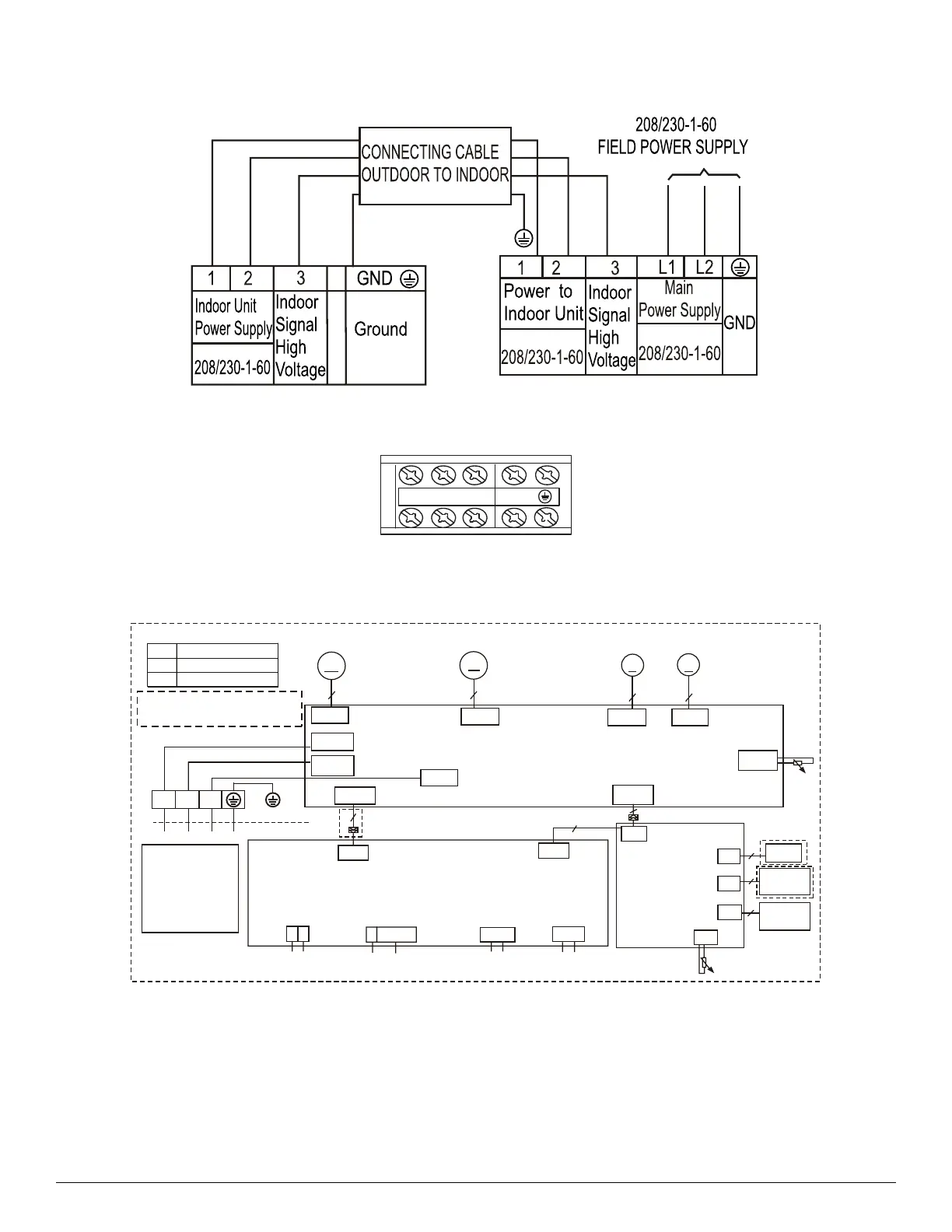
CONNECTION DIAGRAMS
Fig. 1 — Connection Diagram - Size 12K
Fig. 2 — Control and Power Wiring
WIRING DIAGRAM
Fig. 3 — Wiring Diagram - Size 12K
UPPER OUTLET
SWING MOTOR
M
INDOOR FAN1
M
MAIN BOARD
DISPLAY BOARD
4
Wire
Controller
Wi-Fi
5
CN2
4
MULTI-FUNCTION
CONTROL BOARD
CN41
X Y
E 12V/5V
To Remote
Contol
To Remote
Alarm
3
YELLOW(WHITE)
Y/G
RED
N_IN
BLACK
INDOOR UNIT
OUTDOOR UNIT
1 2
L_IN
S
CN12
CN42
INDOOR FAN2
M
CN23
CN19
LOWER OUTLET
SWING MOTOR
CN15
5
5
CN18
CN32
CN5
CN4
Humidity
5
CN1
CN3
CN43
CN40
CN46
CN45
CN42
Note1 :COMPONENT IN DASH LINE
IS OPTIONAL OR FIELDWIRING.
3
T1
T2
M
ROOM TEMP.SENSOR
PIPE TEMP.SENSOR
CODE
PART NAME
T1
T2
5
5
2
Sensor
To 485 Wire-controller
Input:5VDC
Input:5VDC
Output:310VDC
Output:310VDC Output:12VDC
Output:12VDC
Output:5VDC/12VDC
Output:5VDC/12VDC
Input:230VAC
Input:230VAC
Output:0-24VDC
Output:5VDC
Output:5VDC
Output:5VDC
Output:5VDC
Output:0~5VDC
Output:5VDC
Output:0~5VDC
Input:12VDC
Output:12VDC
Note2:
The programmable
wired controller and
CCM COMM.BUS
use the same port
CN42 CN41
DRY CONTACT
 Loading...