14
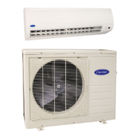
LEGEND:
TXV – Thermostatic Expansion Valve
NOTE: Component location arrangemetshown for field installation of
sight glasses, solenoid valves, filter driers, and TXV sensing bulbs.
The TXVs and equilizer lines are factory installed.
UPPER
SPLIT
AIRFLOW
LOWER
SPLIT
AIRFLOW
15 DIAMS
MIN
10
DIAMS
8 DIAMS
MIN
TXV
SENSING
BULB
EQUALIZER LINE
SIGHT
GLASS
TXV
SOLENOID
VALVE
FILTER
DRIER
TXV
SENSING
BULB
TXV
8 DIAMS
MIN
15 DIAMS
MIN
10
DIAMS
INDOOR
COIL
EQUALIZER
LINE
Single Circuit Coil Piping Configuration - RU*07, 08
For single compressor condensing units.
Dual Circuit Coil Piping Configuration - RU*12-16
For single compressor condensing units
UPPER
SPLIT
AIRFLOW
15 DIAMS
MIN
10
DIAMS
8 DIAMS
MIN
TXV
SENSING
BULB
EQUALIZER LINE
SIGHT
GLASS
TXV
SOLENOID
VALVE
FILTER
DRIER
C10687
Fig. 9 -- Face--Split Coil Suction and Liquid Line Piping (Typical)
FIRST ON/LAST OFF = B
VERTICAL INSTALLATION
FIRST ON/LAST OFF = A
HORIZONTAL INSTALLATIO N
C10688
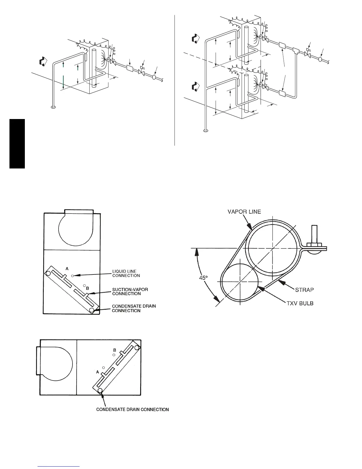
Fig. 10 -- Typical Evaporator Coil Connections (40RU)
LEGEND
TXV — Thermostatic Expansion Valve
NOTE: The 8 o’clock position is shown above.
C10689
Fig. 11 -- TXV Sensing Bulb Location
40RU

 Loading...