GB - 9
42 GW
ENGLISH
• The unit control circuit only allows opening of the motorized
valve when the fan motor is working.
(See wiring diagrams)
• When the thermostat asks for cooling, terminal 2 of TB3 (cold
water) is supplied with 230V.
When it asks for heating, terminal 3 of TB3 (hot water) is
supplied with 230V.
• In both cases terminal 1 of TB3 (possible air renewal fan
motor) is also supplied with 230V.
• The control circuit ensures that the condensate discharge
pump works continuously while the thermostat, asking for
cooling, keeps the cold water regulating valve open.
WARNING :
The valve is not only necessary to control the room
temperature, but also to stop the cold water flow to the coil
in case of an abnormal condensing water level rise in the
drain pan.
• If there is an abnormal condensing water rise in the drain pan
(for example: possible defective drain, pump malfunction, fan
motor not working) causing the opening of the float switch
contact (FS), the control circuit either operates the conden-
sate drain pump, or at the same time closes the regulating
valve, stopping the cold water flow towards the coil and
avoiding further condensation.
Control
The water flow has to be controlled:
• by installing the motorized thermo-electric valves supplied
as accessory
or
• by installing motorized field supplied valves.
Motorized valve and control
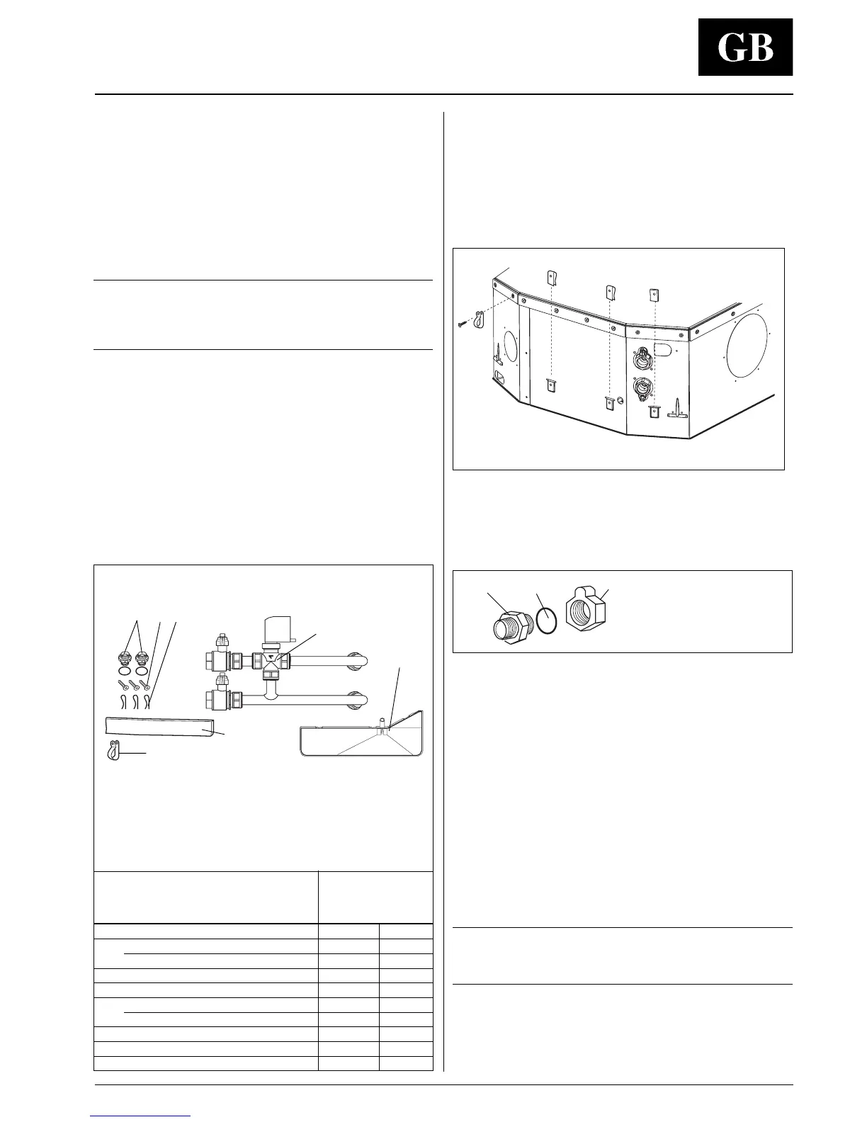
Instructions for mounting of motorized
thermo-electric valve assembly
(see "Components" table)
• The thermo-electric valve must be mounted on the unit after
the unit installation.
For this operation follow figures, depending on model.
• Insert the clips supplied in the unit side slots.
Electric connections
• To connect valves to the electric panel pass cables through
the electric panel grommet and connect them to the terminal
board TB3 as per the wiring diagrams.
Water connections
• Position gas reducers (see table) on the coil connection after
slightly lubricating the O-ring. Mount the O-ring towards the
coil coupling.
• Connect the valve group to the coil and fully tighten fittings.
Fittings should be tightened with a torque of 29.4 Nm.
• Insulate the valve assembly.
• Pass cables through the cable holder G and fix them to the
case using the already pre-assembled screws.
• Mount the drain pan below the valve assembly, inserting the
discharge pipe into the special hole; align and fix it to the 3
clips previously assembled using the three screws supplied.
• Insulate the 3 screws and the drain pan lower part using the
insulating material F.
• To connect the steel pipes to the system, ensure they are
aligned and supported to avoid excess strain on the unit. If
the system is filled with water, check all fitting seals.
NOTE:
The seal efficiency of the valve assembly is factory tested.
Any system losses are therefore due to an incorrect
installation.
A B
C
E
F
G
Water inlet
Water outlet
D
Motorized thermo-electric valve assembly and components
004 012
Mod. 42GW
008 016
010 020
2-pipe
Ref. Description q.ty q.ty
A Adaptor 3/4 " gas with O-ring 2
Adaptor 1" gas with O-ring 1
B Self tapping screw 3 3
C Clip 3 3
D Valve 3/4" gas pre-assembled 1
Valve 1" gas pre-assembled 1
E Auxiliary drain pan 1 1
F Insulating material 1 1
G Cable holder 1 1
Adaptor
O-ring
Coil coupling
 Loading...