GB - 11
42 GW
ENGLISH
Motorized valve and control
• If these connections are not made as described the drain
pan condensate may overflow.
• It is important to close the flow control valves when the indoor
unit control is opened between terminals 4 and 5.
The contact between terminals 4 and 5 opens when the unit is
deenergized and when the drain pan water level is too high.
• Valves should only open when the fan motor is working, i.e.
when one of TB1 terminals 1 or 2 or 3 is supplied from TB1
terminal 4.
• The water discharge pump should work every time the
cold water valve is opened, supplying TB1 terminal 7
and 8 from TB1 terminal 4.
• When the system is filled with water, verify all couplings
for tightness.
• The manufacturer does not accept responsibility for the
tightness of the field - installed valve assembly and this
is not tested in the factory. He declines any responsibility
for non functioning of these assemblies and for damage
due to dripping.
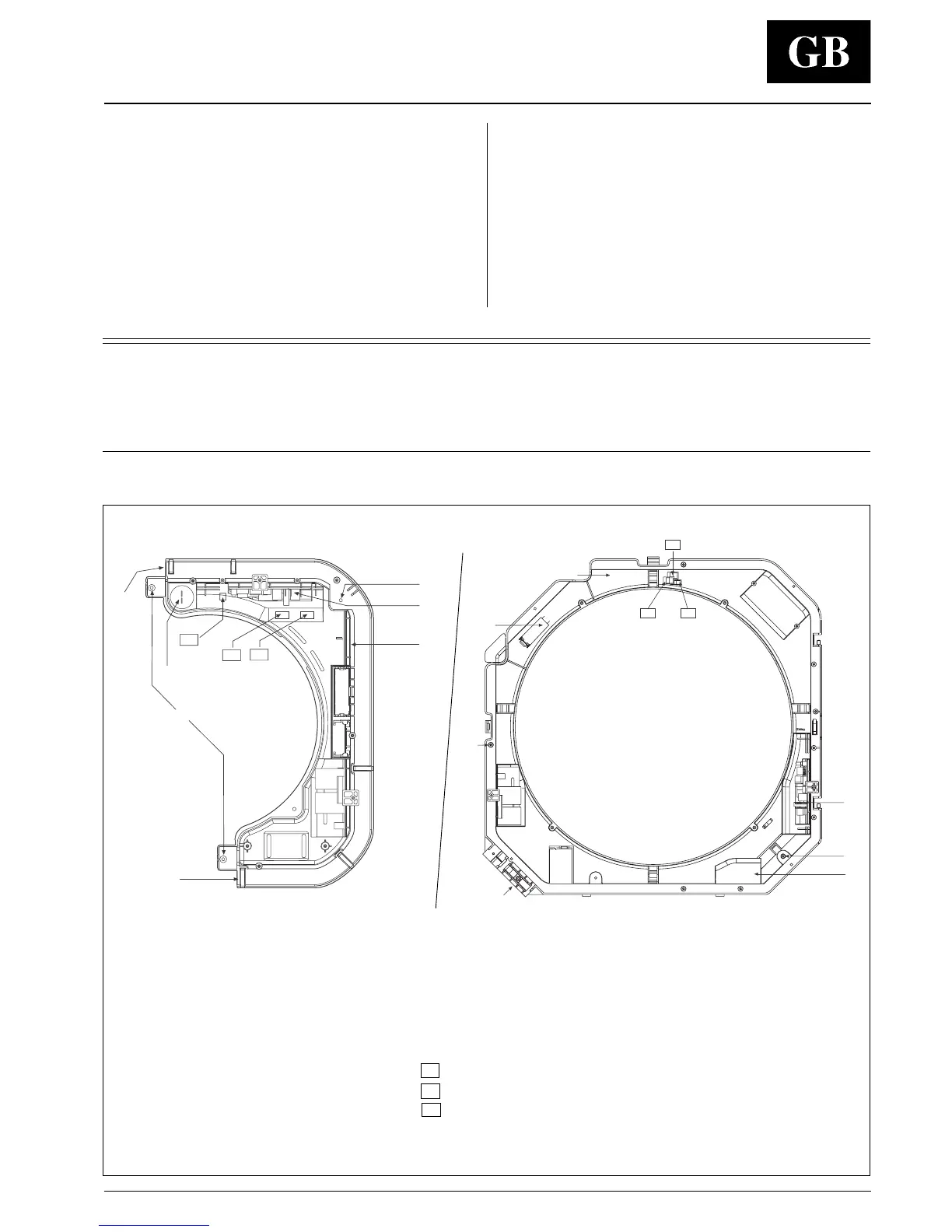
Electrical connections
Capacitor
Ground connection screw
Board
Holes for panel fixing screws
Auxiliary board (accessory)
B
A
CV
CG
CP
STANDARD version unit - Control panel
CV
CG CP
B
A
A. Unit power supply connection
B. Polarised connector
mod. 004 - 008 - 010
mod. 012 - 016 - 020
CV
CG
CP
Fan connector
Float connector
Pump connector
 Loading...