24
4. Secure field ground wire to green ground screw on J--Box
bracket.
5. Connect line voltage leads as shown in Fig. 25.
6. Reinstall cover to J--Box. Do not pinch wires between
cover and bracket.
24--V
WIRING
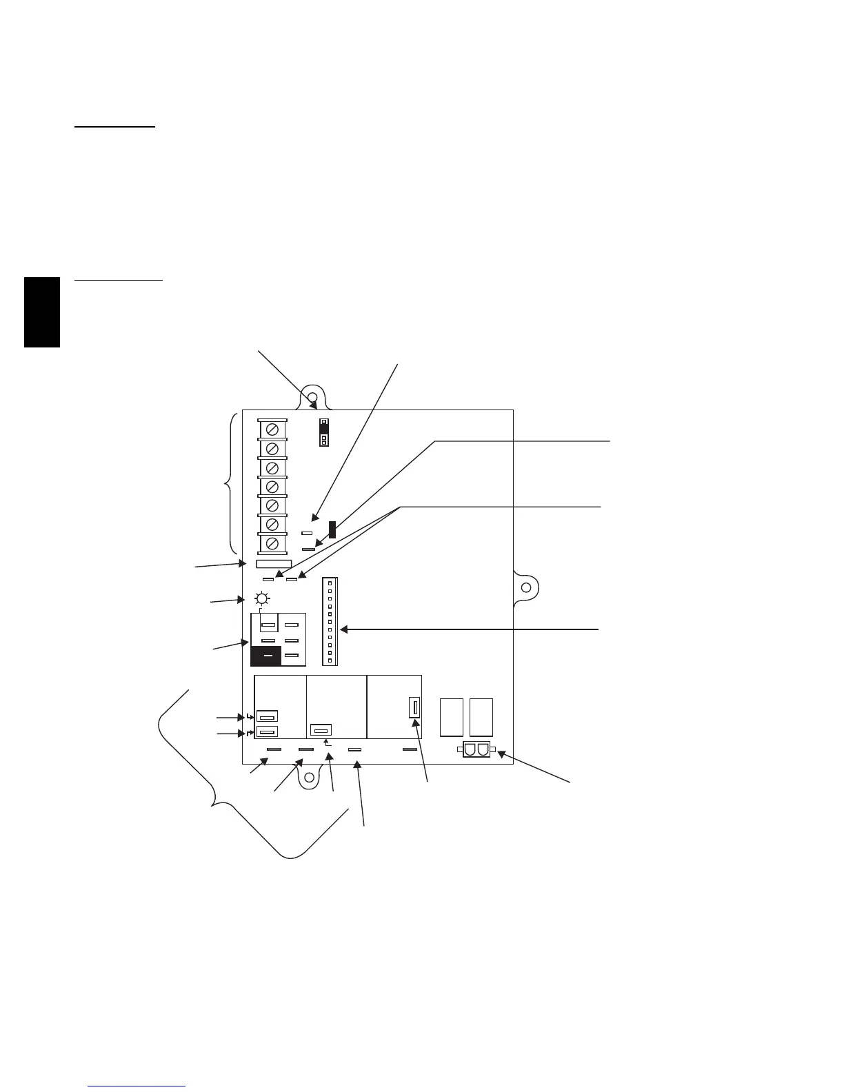
Make field 24--v connections at the 24--v terminal strip. (See Fig.
23.) Connect terminal Y/Y2 as shown in Fig. 24 for proper
cooling operation. Use only AWG No. 18, color--coded, copper
thermostat wire.
The 24--v circuit contains an automotive--type, 3--amp. fuse
located on the control. Any direct shorts during installation,
service, or maintenance could cause this fuse to blow. If fuse
replacement is required, use ONLY a 3--amp. fuse of identical
size.
ACCESSORIES
1. Electronic Air Cleaner (EAC)
Connect an accessory Electronic Air Cleaner (if used) us-
ing 1/4--in female quick connect terminals to the two male
1/4--in quick--connect terminals on the control board
marked EAC--1 and EAC--2. The terminals are rated for
115 VAC, 1.0 amps maximum and are energized during
blower motor operation. (See Fig. 24.)
2. Humidifier (HUM)
Connect an accessory 24 VAC, 0.5 amp. maximum hu-
midifier (if used) to the 1/4--in male quick--connect HUM
terminal and COM--24V screw terminal on the control
board thermostat strip. The HUM terminal is energized
when gas valve relay (GVR) is energized. (See Fig. 24.)
NOTE: A field--supplied, 115--v controlled relay connected to
EAC terminals may be added if humidifier operation is desired
during blower operation.
NOTE: DO NOT connect furnace control HUM terminal to
HUM (humidifier) terminal on Thermidistatt, Zone Controller
or similar device. See Thermidistat, Zone Controller, thermostat,
or controller manufacturer’s instructions for proper connection.
BLW
NUETRAL
STATUS CODE LED
SEC-2 SEC-1
EAC-2 L2
FUSE 3-AMP
0.5 AMP@24VAC
HUM
TEST/TWIN
Y1 DHUM G COM W/W1 Y/Y2 R
24V
PLT
120 180
90 150
BLOWER OFF-DELAY
PLT 1
COOL HEAT
SPARE-1 SPARE-2
FAN
EAC-1
1-AMP@
115VAC
PR-1
L1
PL2 1
24-V THERMOSTAT
TERMINALS
3-AMP FUSE
LED OPERATION &
DIAGNOSTIC LIGHT
115-VAC(L2)NEUTRAL
CONNECTIONS
COOL
HEAT
SPARE-1
SPARE-2 FAN
BLOWER SPEED
SELECTION TERMINALS
EAC-1 TERMINAL
(115-VAC 1.0 AMP MAX.)
115 VAC (L1) LINE
VOLTAGE CONNECTION
PL2-HOT SURFACE
IGNITER & INDUCER
MOTOR CONNECTOR
PL1-LOW VOLTAGE MAIN
HARNESS CONNECTOR
TRANSFORMER 24-VAC
CONNECTIONS
HUMIDIFIER TERMINAL
(24-VAC 0.5 AMP MAX.)
TWINNING AND/OR
COMPONENT TEST
TERMINAL
BLOWER OFF-DELAY
A02142
Fig. 24 -- Furnace Control
58DL
 Loading...