light assistance or a probe can be inserted for sampling the air
stream. The cover attachment shall prevent leaks.
Step 2—Ductwork Acoustical Treatment
Metal duct systems that do not have a 90 degree elbow and 10 ft
of main duct to the first branch take-off may require internal
acoustical lining. As an alternative, fibrous ductwork may be used
if constructed and installed in accordance with the latest edition of
SMACNA construction standard on fibrous glass ducts. Both
acoustical lining and fibrous ductwork shall comply with NFPA
90B as tested by UL Standard 181 for Class 1 Rigid air ducts.
Step 3—Supply Air Connections
UPFLOW FURNACES
Connect supply-air duct to 3/4-in. flange on furnace supply-air
outlet. The supply-air duct attachment must ONLY be connected
to furnace supply-/outlet-air duct flanges or air conditioning coil
casing (when used). DO NOT cut main furnace casing to attach
supply side air duct, humidifier, or other accessories. All accesso-
ries MUST be connected external to furnace main casing.
DOWNFLOW FURNACES
Connect supply-air duct to supply-air opening on furnace. The
supply-air duct attachment must ONLY be connected to furnace
supply/outlet or air conditioning coil casing (when used), when
installed on non-combustible material. When installed on combus-
tible material, supply-air duct attachment must ONLY be con-
nected to an accessory subbase or factory approved air condition-
ing coil casing. DO NOT cut main furnace casing to attach supply
side air duct, humidifier, or other accessories. All accessories
MUST be connected external to furnace main casing. Supply air
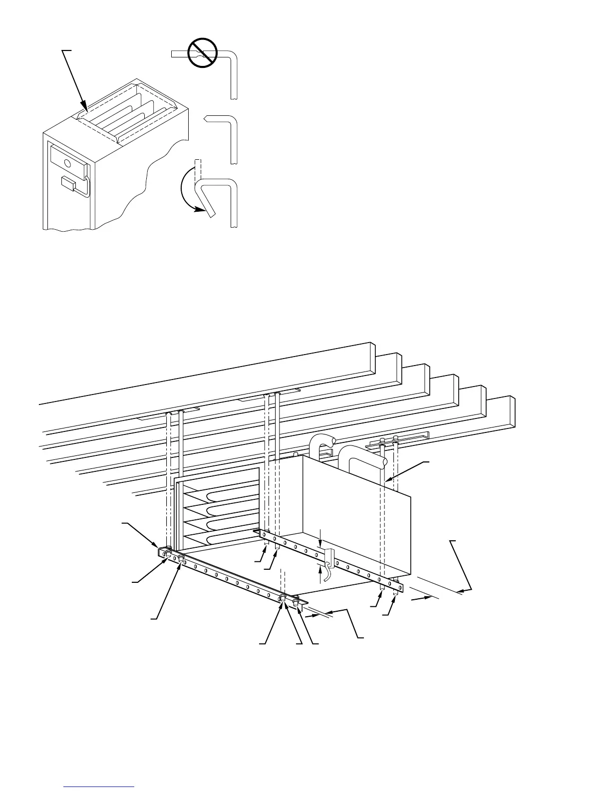
opening duct flanges must be modified per Fig. 21.
HORIZONTAL FURNACES
Connect supply-air duct to supply air opening on furnace. The
supply-air duct attachment must ONLY be connected to furnace
Fig. 21—Duct Flanges
A93029
NO
YES
YES
PERFORATED
DISCHARGE DUCT
FLANGE
210°
MIN
Fig. 22—Crawlspace Horizontal Application
A93304
NOTES:
ANGLE
IRON OR
EQUIVALENT
(B)
(A) ROD LOCATION
USING DIMPLE
LOCATORS
(SEE DIMENSIONAL
DWG FOR
LOCATIONS)
13
/16-IN. MAX
ALTERNATE SUPPORT
LOCATION FROM BACK
ALTERNATE SUPPORT
LOCATION 4-IN. MIN
8-IN. MAX
3
⁄8-IN. ROD
(A)
(B)
(A)
(B)
(B)
(A)
1. A 1 In. clearance minimum between top of
furnace and combustible material.
2. The entire length of furnace must be
supported when furnace is used in horizontal
position to ensure proper drainage.
(A) PREFERRED ROD LOCATION
(B) ALTERNATE ROD LOCATION
DRAIN
5
3
⁄
4
″
3
/8-IN. HEX NUT
& WASHER (4)
REQD PER ROD
16
 Loading...


