10. Wipe excess cement from joint. A continuous bead of cement
will be visible around perimeter of a properly made joint.
11. Handle pipe joints carefully until cement sets.
12. Support combustion-air and vent piping a minimum of every
5 ft (3 ft for SDR-21 or -26 PVC) using perforated metal
hanging strap.
13. Slope combustion-air and vent pipes downward toward fur-
nace a minimum of 1/4 in. per linear ft with no sags between
hangers.
14. Use appropriate methods to seal openings where vent and
combustion-air pipes pass through roof or side wall.
Step 3—Concentric Vent and Combustion-Air
Termination Kit Installation
NOTE: If these instructions differ from those packaged with
termination kit, follow kit instructions.
Combustion-air and vent pipes must terminate outside structure. A
factory accessory termination kit must be installed in 1 of the
installations shown in Fig. 36, 37, 38, 39, and 40. Four termination
kits are available.
1. The 2-in. termination bracket kit is for 1-in., 1-1/2 in., and
2-in. diameter 2-pipe termination systems.
2. The 3-in. termination bracket kit is for 2-1/2 in., 3-in., and
4-in. diameter 2-pipe termination systems.
3. The 2-in. concentric vent/air termination kit is for 1-in., 1-1/2
in., 2-in., and 2-1/2 in. diameter pipe systems when single
penetration of wall or roof is desired.
4. The 3-in. concentric vent/air termination kit is for 2-1/2 in.,
3-in., and 4-in. diameter pipe systems when single penetration
of wall or roof is desired.
Table 7—Maximum Allowable Pipe Length (ft) (Continued)
ALTITUDE (FT) UNIT SIZE
TERMINATION
TYPE
PIPE DIA
(IN.)*
NUMBER OF 90° ELBOWS
123456
8001 to 9000‡
040-08
040-12
2 Pipe or 2-in
Concentric
1-1/2 46 41 36 31 29 24
2 626058565553
060-08
060-12
060-16
2 Pipe or 2-in
Concentric
1-1/2 11 6 NA NA NA NA
2 494442373534
080-12
080-16
080-20
2 Pipe or 2-in
Concentric
2 3328171210NA
2-1/2 62 60 58 56 55 53
100-16
100-20
2 Pipe or 3-in
Concentric
2-1/2 23 15 7 5 NA NA
3 595449443934
120-20
2 Pipe or 3-in.
Concentric
3† no disk 10 NA NA NA NA NA
4† no disk 35 30 25 20 15 10
140-20 NA
ALTITUDE (FT) UNIT SIZE
TERMINATION
TYPE
PIPE DIA
(IN.)*
NUMBER OF 90° ELBOWS
123456
9001 to 10,000‡
040-08
040-12
2 Pipe or 2-in
Concentric
1-1/2 42 37 32 27 25 20
2 575553514947
060-08
060-12
060-16
2 Pipe or 2-in
Concentric
2 454038333129
080-12
080-16
080-20
2 Pipe or 2-in
Concentric
230251497NA
2-1/2 57 55 53 51 49 47
100-16
100-20
2 Pipe or 3-in
Concentric
2-1/2 21 13 5 NA NA NA
3 544944393429
120-20
2 Pipe or 3-in.
Concentric
4† no disk 10 5 NA NA NA NA
140-20 NA
Disk usage-Unless otherwise specified, use perforated disk assembly (factory-supplied in loose parts bag). If one disk is stated, separate 2 halves of perforated disk
assembly and use shouldered disk half. When using shouldered disk half, install screen side toward inlet box.
†Wide radius elbow.
‡Vent sizing for Canadian installations over 4500 ft (1370 m) above sea level are subject to acceptance by the local authorities having jurisdiction.
NA-Not Allowed; pressure switch will not make.
NOTES:
1. Do not use pipe size greater than those specified in table or incomplete combustion, flame disturbance, or flame sense lockout may occur.
2. Size both the combustion-air and vent pipe independently, then use the larger diameter for both pipes.
3. Assume two 45° elbows equal one 90° elbow. Long radius elbows are desirable and may be required in some cases.
4. Elbows and pipe sections within the furnace casing and at the vent termination should not be included in vent length or elbow count.
5. The minimum pipe length is 5 ft for all applications.
6. Use 3-in. diameter vent termination kit for installations requiring 4-in diameter pipe.
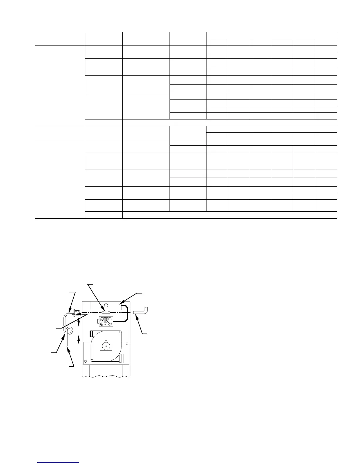
Fig. 35—Air Intake Housing Plug Fitting Drain
A93035
COMBUSTION –
AIR PIPE
BURNER
BOX
COMBUSTION – AIR
INTAKE HOUSING
3/8" ID TUBE
TRAP
TO OPEN
DRAIN
3/16"
DRILL
4″
MIN
29
 Loading...


