58SB0B/58SB1B: Installation, Start–Up, Operating and Service and Maintenance Instructions
Manufacturer reserves the right to change, at any time, specifications and designs without notice and without obligations.
14
Refer to Table 5 for recommended gas pipe sizing. Risers must be used
to connect to furnace and to meter. Support all gas piping with
appropriate straps, hangers, etc. Use a minimum of 1 hanger every 6 ft.
(2 M). Joint compound (pipe dope) should be applied sparingly and only
to male threads of joints. Pipe dope must be resistant to the action of
propane gas.
* Cubic ft. of natural gas per hr for gas pressures of 0.5 psig (14-in. w.c.) or less and a
pressure drop of 0.5-in. w.c. (based on a 0.60 specific gravity gas). Ref: Chapter 6 current
edition of ANSI Z223/NFPA 54.
An accessible manual equipment shutoff valve MUST be installed
external to furnace casing and within 6 ft. (2 M) of furnace. A 1/8-in. (3
mm) NPT plugged tapping, accessible for test gauge connection, MUST
be installed immediately upstream of gas supply connection to furnace
and downstream of manual equipment shutoff valve.
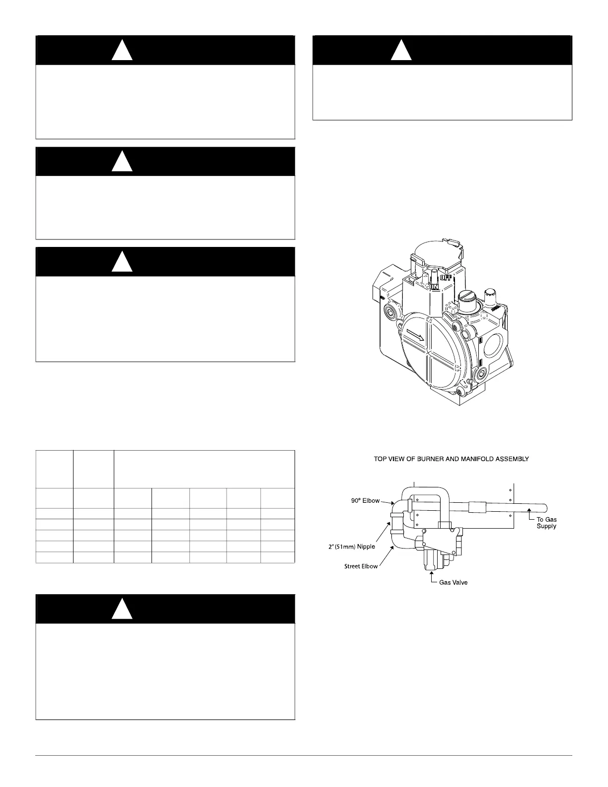
NOTE: The furnace gas control valve inlet pressure tap connection is
suitable to use as test gauge connection providing test pressure DOES
NOT exceed maximum 0.5 psig (14-in. w.c.) stated on gas control valve
(see Fig. 21).
A06666
Fig. 21 – Gas Control Valve
Some installations require gas entry on right side of furnace (as viewed
in upflow.) (See Fig. 22).
A08551
Fig. 22 – Burner and Manifold
Install a sediment trap in riser leading to furnace (see Fig. 23). Connect a
capped nipple into lower end of tee. Capped nipple should extend below
level of furnace gas controls. Place a ground joint union between furnace
gas control valve and exterior manual equipment gas shutoff valve.
A 1/8-in. (3 mm) NPT plugged tapping, accessible for test gauge
connection, MUST be installed immediately upstream of gas supply
connection to furnace and downstream of manual equipment shutoff
valve.
WARNING
!
FIRE OR EXPLOSION HAZARD
Failure to follow this warning could result in personal injury, death,
and/or property damage.
Never purge a gas line into a combustion chamber. Never test for gas
leaks with an open flame. Use a commercially available soap solution
made specifically for the detection of leaks to check all connections.
WARNING
!
FIRE OR EXPLOSION HAZARD
Failure to follow this warning could result in personal injuriousness,
and/or property damage.
Use proper length of pipe to avoid stress on gas control assembly and a
gas leak.
WARNING
!
FIRE OR EXPLOSION HAZARD
Failure to follow this warning could result in personal injury, death,
and/or property damage.
Gas valve inlet and/or inlet pipe must remain capped until gas supply
line is permanently installed to protect the valve from moisture and
debris. Also, install a sediment trap in the gas supply piping at the inlet
to the gas valve.
Table 5 – Maximum Capacity of Pipe*
NOMINAL
IRON
PIPE
INTERNAL
DIAMETER
LENGTH OF PIPE - FT. (M)
SIZE IN.
(mm)
In. (mm) 10 20 30 40 50
1/2 (13) 0.622 (16) 175 (53) 120 (37) 97 (30) 82 (25) 73 (22)
3/4 (19) 0.824 (21) 360 (110) 250 (76) 200 (61) 170 (52) 151 (46)
1 (25) 1.049 (27) 680 (207) 465 (142) 375 (114) 320 (98) 285 (87)
1-1/4 (32) 1.380 (35) 1400 (427) 950 (290) 770 (235) 660 (201) 580 (177)
1-1/2 (38) 1.610 (41) 2100 (640) 1460 (445) 1180 (360) 990 (301) 900 (274)
WARNING
!
FIRE OR EXPLOSION HAZARD
Failure to follow this warning could result in personal injury, death,
and/or property damage.
If local codes allow the use of a flexible gas appliance connector,
always use a new listed connector. Do not use a connector which has
previously served another gas appliance. Black iron pipe shall be
installed at the furnace gas control valve and extend a minimum of 2
in.(51 mm) outside the furnace.
CAUTION
!
FURNACE OVERHEAT HAZARD
Failure to follow this caution may result in property damage.
Connect gas pipe to gas valve using a backup wrench to avoid
damaging gas controls and burner misalignment.

 Loading...