58SB0B/58SB1B: Installation, Start–Up, Operating and Service and Maintenance Instructions
Manufacturer reserves the right to change, at any time, specifications and designs without notice and without obligations.
38
5. Inspect the vent pipe/vent system before each heating season for
rust, corrosion, water leakage, sagging pipes or broken fittings.
Have vent pipes/vent system serviced by a qualified service agency.
6. Inspect any accessories attached to the furnace such as a humidifier
or electronic air cleaner. Perform any service or maintenance to the
accessories as recommended in the accessory instructions.
Cleaning and/or Replacing Air Filter
The air filter arrangement will vary depending on the application. The
filter is exterior to the furnace casing.
NOTE: If the filter has an airflow direction arrow, the arrow must point
towards the blower.
To clean or replace filters, proceed as follows:
1. Turn off electrical supply to furnace before removing filter access
door.
2. Remove filter cabinet door.
3. Slide filter out of cabinet.
4. If equipped with permanent, washable 3/4-in. (19 mm) filter, clean
filter by spraying cold tap water through filter in opposite direction
of airflow. Rinse filter and let dry. Oiling or coating of the filter is
not recommended. See Table 18 for size information.
5. If equipped with factory-specified disposable media filter, replace
only with media filter having the same part number and size. For
expandable replacement media, refer to the instructions included
with the replacement media.
6. Slide filter into cabinet.
7. Replace filter cabinet door.
8. Turn on electrical supply to furnace.
Blower Motor and Wheel Maintenance
NOTE: The blower wheel should not be dropped or bent as balance will
be affected. The following steps should be performed by a qualified
service agency.
To ensure long life and high efficiency, clean accumulated dirt and
grease from blower wheel and motor annually.
The inducer and blower motors are pre-lubricated and require no
additional lubrication. These motors can be identified by the absence of
oil ports on each end of the motor. The following steps should be
performed by a qualified service agency.
Clean blower motor and wheel as follows:
1. Turn off electrical supply to furnace.
2. Remove outer door.
3. For downflow or horizontal furnaces having vent pipes within the
furnace that pass in front of the blower access door:
a. Disconnect vent connector from furnace vent elbow.
b. Disconnect and remove short piece of vent pipe from within
furnace.
4. Remove two screws from blower access door and remove blower
access door.
5. All factory wires can be left connected, but field thermostat
connections may need to be disconnected depending on their length
and routing.
NOTE: The blower wheel should not be dropped or bent as balance will
be affected.
6. Remove two screws holding blower assembly to blower deck and
slide blower assembly out of furnace.
7. Clean blower wheel and motor using a vacuum with soft brush
attachment. Blower wheel blades may be cleaned with a small paint
or flux brush. Do not remove or disturb balance weights (clips) on
blower wheel blades.
8. Vacuum any loose dust from blower housing, wheel and motor.
9. If a greasy residue is present on blower wheel, remove wheel from
the blower housing and wash it with an appropriate degreaser.
NOTE: Before disassembly, mark blower motor, and blower housing so
motor and each arm is positioned at the same location during
reassembly.
To remove wheel:
a. Disconnect power choke wires (if used) and ground wire
attached to blower housing.
b. Remove screws securing cutoff plate and remove cutoff plate
from housing.
c. Loosen set screw holding blower wheel on motor shaft (160+/-20
in.-lb. when reassembling).
d. Remove bolts holding motor to blower housing and slide motor
out of wheel (40+/-10 in.-lb. when reassembling).
e. Remove blower wheel from housing.
f. Clean wheel and housing.
10. Reassemble motor and blower by reversing steps 9f through 11a,
finishing with 9a. Be sure to reattach ground wire to the blower
housing.
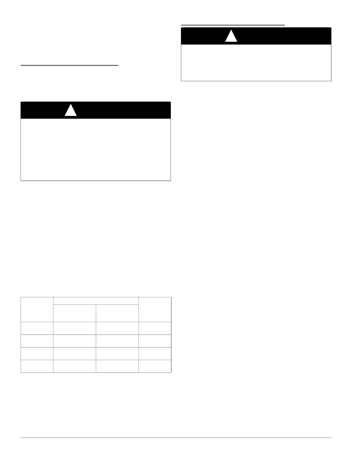
WARNING
!
ELECTRICAL SHOCK, FIRE OR EXPLOSION HAZARD
Failure to follow this warning could result in personal injury or death,
or property damage.
Before installing, modifying, or servicing system, main electrical
disconnect switch must be in the OFF position and install a lockout tag.
There may be more than one disconnect switch. Lock out and tag
switch with a suitable warning label. Verify proper operation after
servicing. Always reinstall access doors after completing service and
maintenance.
Table 18 – Filter Size Information (In. / mm)
FURNACE
CASING
WIDTH
In. (mm)
FILTER SIZE (In. / mm)
FILTER
TYPE
*
*. Recommended
Side Return Bottom Return
14-1/2
(368)
16 x 25 x 3/4
(406 x 635 x 19)
14 x 25 x 3/4
(356 x 635 x 19)
Washable
17-1/2
(445)
16 X 25 X 3/4
(406 x 635 x 19)
16 X 25 X 3/4
(406 x 635 x 19)
Washable
21
(533)
16 x 25 x 3/4
(406 x 635 x 19)
20 X 25 X 3/4
(508 x 635 x 19)
Washable
24
(610)
16 x 25 x 3/4
(406 x 635 x 19)
24 X 25 X 3/4
(610 x 635 x 19)
Washable
WARNING
!
ELECTRICAL SHOCK HAZARD
Failure to follow this warning could result in personal injury or death.
Blower access door switch opens 115-V power to control. No
component operation can occur unless switch is closed. Caution must
be taken when manually closing this switch for service purposes.

 Loading...