58SB0B/58SB1B: Installation, Start–Up, Operating and Service and Maintenance Instructions
Manufacturer reserves the right to change, at any time, specifications and designs without notice and without obligations.
16
\
A190279
Fig. 25 – Field-Supplied External Electrical Box on Furnace Casing
J-BOX RELOCATION
NOTE: If factory location of J-Box is acceptable, go to next section
(ELECTRICAL CONNECTION TO J-BOX).
NOTE: On 14-in. (356 mm) wide casing models, the J-Box shall not be
relocated to other side of furnace casing when the vent pipe is routed
within the casing.
1. Remove and save two screws holding J-Box.
NOTE: The J-Box cover need not be removed from the J-Box in order
to move the J-Box. Do NOT remove green ground screw inside J-Box
(see Fig. 26).
2. Cut wire tie on loop in furnace wires attached to J-box.
3. Move J-Box to desired location.
4. Fasten J-Box to casing with two screws removed in Step 1.
5. Route J-Box wires within furnace away from sharp edges, rotating
parts and hot surfaces.
A10291
Fig. 26 – Relocating J-Box
Electrical Connection to J-Box
Electrical Box on Furnace Casing Side
1. Refer to Fig. 27 when installing an electrical box.
2. Select and remove a hole knockout in the casing where the
electrical box is to be installed.
NOTE: Check that duct on side of furnace will not interfere with
installed electrical box.
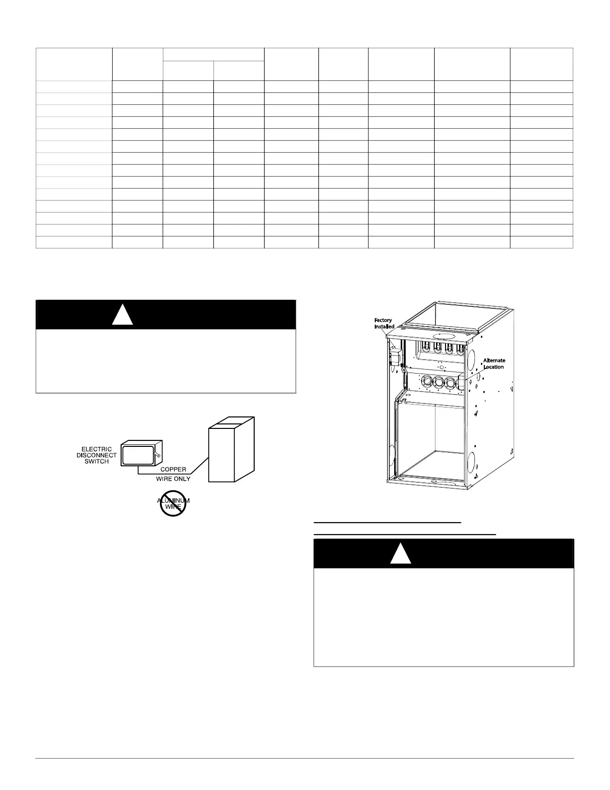
Table 6 – Electrical Data
Unit Size
Volts-
Hertz-
Phase
Operating Voltage
*
Range
*. Permissible limits of the voltage range at which the unit operates satisfactorily.
Maximum
Unit
Amps
Unit
Ampacity
†
†. Unit ampacity = 125 percent of largest operating component’s full load amps plus 100 percent of all other potential operating components’ (EAC, humidifier, etc.) full load
amps.
Minimum Wire
Size AWG
Maximum Wire
Length
‡
Ft. (M)
‡. Length shown is as measured one way along wire path between unit and service panel for maximum 2 percent voltage drop.
Maximum Fuse
or CKT BKR
Amps
**
**. Time-delay type is recommended.
Maximum Minimum
045M14--12 115-60-1 127 104 6.0 8.3 14 44 (13.6) 15
045M17--14 115-60-1 127 104 7.9 10.7 14 34 (10.6) 15
070M14--12 115-60-1 127 104 6.0 8.3 14 44 (13.6) 15
070M17--12 115-60-1 127 104 5.9 8.2 14 45 (13.8) 15
070M17--16 115-60-1 127 104 10.4 13.8 14 26 (8.2) 15
070M21--16 115-60-1 127 104 10.4 13.8 14 26 (8.2) 15
090M17--14 115-60-1 127 104 8.2 11.0 14 34 (10.3) 15
090M21--16 115-60-1 127 104 8.2 11.0 14 34 (10.3) 15
090M21--20 115-60-1 127 104 13.9 18.1 12 31 (9.6) 20
090M24--20 115-60-1 127 104 10.7 14.1 14 26 (8.0) 15
110M21--20 115-60-1 127 104 14.4 18.6 12 30 (9.4) 20
110M24--20 115-60-1 127 104 11.1 14.6 14 25 (7.7) 15
135M24--20 115-60-1 127 104 11.0 14.4 14 25 (7.8) 15
155M24--20 115-60-1 127 104 10.7 14.1 14 26 (8.0) 15
WARNING
!
FIRE HAZARD
Failure to follow this warning could result in personal injury, death, or
property damage.
Do not connect aluminum wire between disconnect switch and furnace.
Use only copper wire (see Fig. 25).
WARNING
!
FIRE OR ELECTRICAL SHOCK HAZARD
Failure to follow this warning could result in personal injury, death, or
property damage.
High voltage field connections must be located in J-Box with furnace,
or in field supplied external disconnect mounted to furnace.
If field-supplied manual disconnect switch is to be mounted on furnace
casing side, select a location where a drill or fastener cannot damage
electrical or gas components.
 Loading...