58SB0B/58SB1B: Installation, Start–Up, Operating and Service and Maintenance Instructions
Manufacturer reserves the right to change, at any time, specifications and designs without notice and without obligations.
33
1. Determine the correct gas input rate.
The input rating for altitudes above 2,000 ft. (610 M) must be
reduced by 4 percent for each 1,000 ft. (305 M) above sea level. For
installations below 2000 ft. (610 M), refer to the unit rating plate.
For installations above 2000 ft. (610 M), multiply the input on the
rating plate by the de-rate multiplier in Table 14 for the correct
input rate.
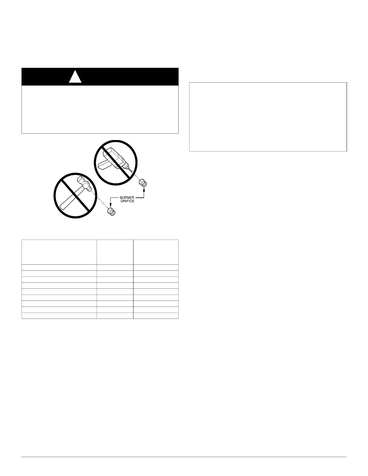
A93059
Fig. 47 – Orifice Hole
2. Determine the correct orifice and manifold pressure adjustment.
There are two different orifice and manifold adjustment tables. All
models in all positions, except Low NOx models in downflow or
horizontal positions, use Table 16 (22,000 BTUh/Burner).
Low NOx models in the downflow or horizontal positions must use
Table 17 (21,000 BTUh/Burner). See input listed on rating plate.
a. Obtain average yearly gas heat value (at installed altitude) from
local gas supplier.
b. Obtain average yearly gas specific gravity from local gas
supplier.
c. Find installation altitude in Table 16 or Table 17.
d. Find closest natural gas heat value and specific gravity in
Table 16 or Table 17.
e. Follow heat value and specific gravity lines to point of
intersection to find orifice size and manifold pressure settings for
proper operation.
f. Check and verify burner orifice size in furnace. NEVER
ASSUME ORIFICE SIZE. ALWAYS CHECK AND VERIFY.
NOTE: If orifice hole appears damaged or it is suspected to have been
redrilled, check orifice hole with a numbered drill bit of correct size.
Never redrill an orifice. A burr-free and squarely aligned orifice hole is
essential for proper flame characteristics.
g. Replace orifice with correct size if required by Table 14,
Table 16, Table 17 and Table 15. Use only factory-supplied
orifices. See EXAMPLE 1.
3. Adjust manifold pressure to obtain correct input rate.
a. Turn gas valve ON/OFF switch to OFF.
b. Remove manifold pressure tap plug from gas valve (see Fig. 21).
c. Connect a water column manometer or similar device to
manifold pressure tap.
d. Turn gas valve ON/OFF switch to ON.
e. Manually close blower door switch.
f. Set thermostat to call for heat.
g. Remove regulator seal cap and turn regulator adjusting screw
counterclockwise (out) to decrease input rate of clockwise (in) to
increase input rate.
NOTE: DO NOT set manifold pressure less than 3.2-in. w.c. or more
than 3.8-in. w.c. for natural gas at sea level. If manifold pressure is
outside this range, change main burner orifices. Refer to Table 14,
Table 16, Table 17 and Table 15.
h. Install regulator seal cap.
i. Leave manometer or similar device connected and proceed to
Step 4.
4. Verify natural gas input rate by clocking meter.
NOTE: Gas valve regulator adjustment cap must be in place for proper
input to be clocked.
a. Turn off all other gas appliances and pilots served by the meter.
b. Run furnace for 3 minutes in heating operation.
c. Measure time (in sec) for gas meter to complete 1 revolution and
note reading. The 2 or 5 cubic feet dial provides a more accurate
measurement of gas flow.
d. Refer to Table 16 for cubic ft. of gas per hr.
e. Multiply gas rate (cu ft./hr) by heating value (BTUh/cu ft.) to
obtain input.
f. If clocked rate does not match required input from Step 1,
increase manifold pressure to increase input or decrease manifold
pressure to decrease input. Repeat steps b through e until correct
input is achieved. Reinstall regulator seal cap on gas valve.
CAUTION
!
FURNACE DAMAGE HAZARD
Failure to follow this caution may result in reduced furnace life.
DO NOT redrill orifices. Improper drilling (burrs, out-of-round holes,
etc.) can cause excessive burner noise and misdirection of burner
flames. This can result in flame impingement of heat exchangers,
causing failures (see Fig. 47).
Table 14 – Altitude Derate Multiplier for U.S.A.
ALTITUDE
(FT. / M)
PERCENT
OF
DERATE
DERATE
MULTIPLIER
FACTOR
*
*. Derate multiplier factors are based on midpoint altitude for altitude range
0–2000 (0-610) 0 1.00
2001–3000 (610-914) 8–12 0.90
3001–4000 (914-1219) 12–16 0.86
4001–5000 (1219-1524) 16–20 0.82
5001–6000 (1524-1829) 20–24 0.78
6001–7000 (1829-2134) 24–28 0.74
7001–8000 (2134-2438) 28–32 0.70
8001–9000 (2438-2743) 32–36 0.66
9001–10,000 (2743-3048) 36–40 0.62
EXAMPLE 1: (0 to 2000 ft. (0 to 610 M) altitude)
For 22,000 BTUh per burner application use Table 16.
Heating value = 1000 BTUh/cu ft.
Specific gravity = 0.62
Therefore: Orifice No. 43*
Manifold pressure: 3.7-in. w.c.
*Furnace is shipped with No. 43 orifices.
In this example all main burner orifices are the correct
size and do not need to be changed to obtain proper input rate.
 Loading...