58SC0B/58SC1B: Installation, Start–Up, Operating and Service and Maintenance Instructions
Manufacturer reserves the right to change, at any time, specifications and designs without notice and without obligations.
2
A210785
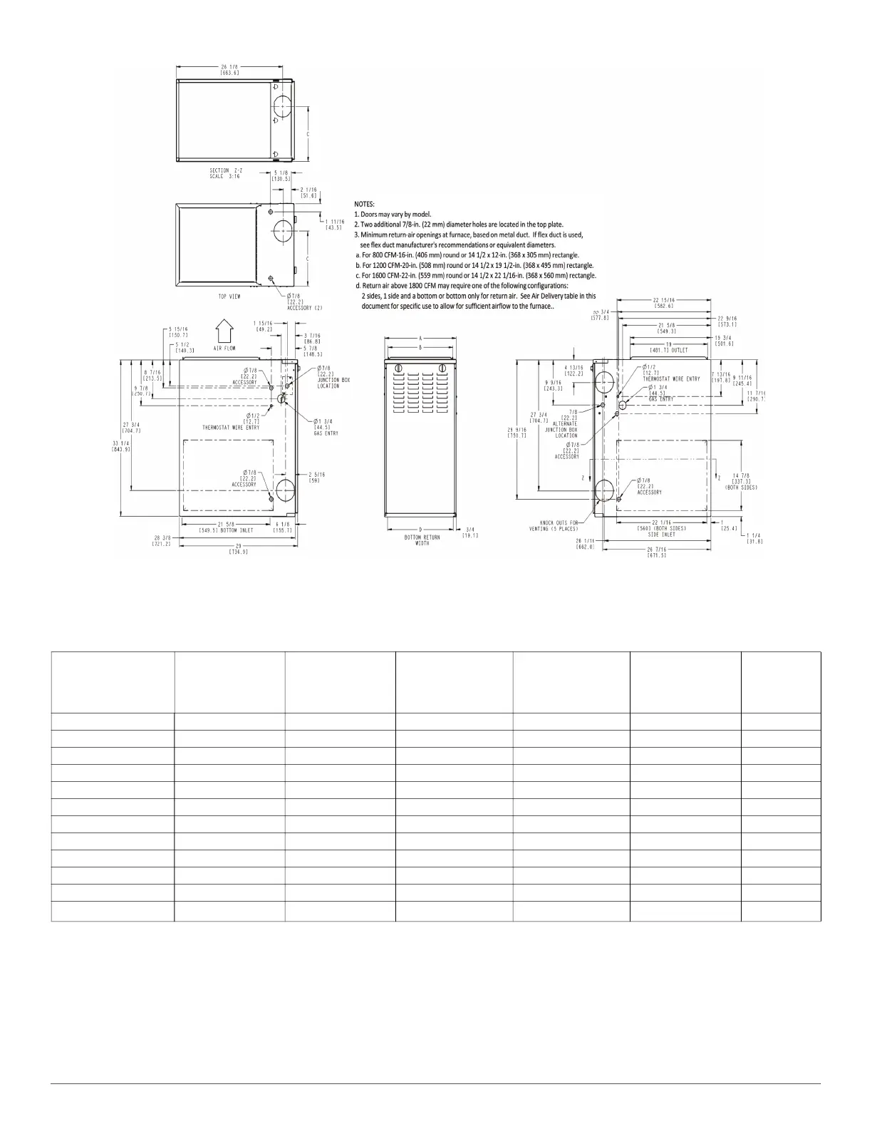
Fig. 1 – Dimensional Drawing
Table 1 – Dimensions
Unit Size
A
CABINET WIDTH
B
OUTLET WIDTH
C
TOP AND
BOTTOM FLUE
COLLAR
D
BOTTOM
INLET WIDTH
VENT
CONNECTION
SIZE
SHIP WT. LB.
(KG)
045M14--12 14-3/16 (360) 12-9/16 (319) 9-5/16 (237) 12-11/16 (322) 4 (102) 108 (49)
045M17--14 17-1/2 (445) 15-7/8 (403) 11-9/16 (294) 16 (406) 4 (102) 121 (55)
070M14--12 14-3/16 (360) 12-9/16 (319) 9-5/16 (237) 12-11/16 (322) 4 (102) 114 (52)
070M17--12 17-1/2 (445) 15-7/8 (403) 11-9/16 (294) 16 (406) 4 (102) 124 (56)
070M17--16 17-1/2 (445) 15-7/8 (403) 11-9/16 (294) 16 (406) 4 (102) 127 (58)
070M21--16 21 (533) 19-3/8 (492) 13-5/16 (338) 19-1/2 (495) 4 (102) 139.5 (63)
090M17--14 17-1/2 (445) 15-7/8 (403) 11-9/16 (294) 16 (406) 4 (102) 133 (60)
090M21--16 21 (533) 19-3/8 (492) 13-5/16 (338) 19-1/2 (495) 4 (102) 140.5 (64)
090M21--20 21 (533) 19-3/8 (492) 13-5/16 (338) 19-1/2 (495) 4 (102) 147 (67)
110M21--20 21 (533) 19-3/8 (492) 13-5/16 (338) 19-1/2 (495) 4 (102) 150 (68)
110M24--20 24-1/2 (622) 22-7/8 (581) 15-1/16 (383) 23 (584) 4 (102) 165 (75)
135M24--20 24-1/2 (622) 22-7/8 (581) 15-1/16 (383) 23 (584)
4 (102)
*
*. 135 size furnaces requires a 5 or 6-in. (127 or 152 mm) vent. Use a vent adapter between furnace and vent stack. See Installation Instructions for complete installation
requirements
167 (76)
U.S. ECCN: Not Subject to Regulation (N.S.R.)
SD5669-4 REV. -
NOTE: ALL DIMENSIONS IN INCH (MM)
 Loading...