58SC0B/58SC1B: Installation, Start–Up, Operating and Service and Maintenance Instructions
Manufacturer reserves the right to change, at any time, specifications and designs without notice and without obligations.
20
Exterior Masonry Chimney FAN + NAT Installations with Type-B
Double Wall Vent Connectors
©
NFPA & AGA
If all of these conditions cannot be met, an alternative venting design
shall be used, such as the listed chimney adapter kit with these furnaces,
which are listed for use with the kit, a listed chimney-lining system, or a
Type-B common vent.
* The 99.6% heating db temperatures found in the 1997 or 2001 ASHRAE Fundamentals
Handbook, Climatic Design Information chapter, Table 1A (United States) or the 2005
ASHRAE Fundamentals handbook, Climatic Design Information chapter, and the
CD-ROM included with the 2005 ASHRAE Fundamentals Handbook.
Inspections before the sale and at the time of installation will determine
the acceptability of the chimney or the need for repair and/or (re)lining.
Refer to the Fig. 30 to perform a chimney inspection. If the inspection of
a previously used tile-lined chimney:
a. Shows signs of vent gas condensation, the chimney should be
relined in accordance with local codes and the authority having
jurisdiction. The chimney should be relined with a listed metal
liner, Type-B vent, or a listed chimney adapter kit shall be used to
reduce condensation. If a condensate drain is required by local
code, refer to the current edition of NFGC NFPA54/ANSI
Z223.1, Section 12.10 for additional information on condensate
drains.
b. Indicates the chimney exceeds the maximum permissible size in
the tables, the chimney should be rebuilt or relined to conform to
the requirements of the equipment being installed and the
authority having jurisdiction.
A chimney without a clay tile liner, which is otherwise in good
condition, shall be rebuilt to conform to current edition of ANSI/NFPA
211 or be lined with a UL listed metal liner or UL listed Type-B vent.
Relining with a listed metal liner or Type-B vent is considered to be a
vent-in-a-chase.
If a metal liner or Type-B vent is used to line a chimney, no other
appliance shall be vented into the annular space between the chimney
and the metal liner.
APPLIANCE APPLICATION REQUIREMENTS
Appliance operation has a significant impact on the performance of the
venting system. If the appliances are sized, installed, adjusted, and
operated properly, the venting system and/or the appliances should not
suffer from condensation and corrosion. The venting system and all
appliances shall be installed in accordance with applicable listings,
standards, and codes.
The furnace should be sized to provide 100 percent of the design heating
load requirement plus any margin that occurs because of furnace model
size capacity increments. Heating load estimates can be made using
approved methods available from Air Conditioning Contractors of
America (Manual J); American Society of Heating, Refrigerating, and
Air-Conditioning Engineers; or other approved engineering methods.
Excessive oversizing of the furnace could cause the furnace and/or vent
to fail prematurely. When a metal vent or metal liner is used, the vent
must be in good condition and be installed in accordance with the vent
manufacturer’s instructions.
To prevent condensation in the furnace and vent system, the following
precautions must be observed:
1. The return-air temperature must be at least 60°F (16°C)db except
for brief periods of time during warm-up from setback at no lower
than 55°F (13°C) db or during initial start-up from a standby
condition.
2. Adjust the gas input rate per the installation instructions. Low gas
input rate causes low vent gas temperatures, causing condensation
and corrosion in the furnace and/or venting system. Derating is
permitted only for altitudes above 2000 ft. (610 M).
3. Adjust the air temperature rise to the midpoint of the rise range or
slightly above. Low air temperature rise can cause low vent gas
temperature and potential for condensation problems.
4. Set the thermostat heat anticipator or cycle rate to reduce short
cycling.
Air for combustion must not be contaminated by halogen compounds
which include chlorides, fluorides, bromides, and iodides. These
compounds are found in many common home products such as
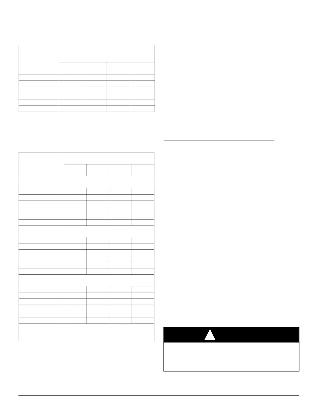
Table 7 – Combined Appliance Maximum Input Rating
in Thousands of BTUh per Hour
VENT HEIGHT
FT. (M)
INTERNAL AREA OF CHIMNEY
IN
2
(MM
2
)
12
(7741)
19
(12258)
28
(18064)
38
(24516)
6 (1.8) 74 119 178 257
8 (2.4) 80 130 193 279
10 (3.0) 84 138 207 299
15 (4.5) NR 152 233 334
20 (6.0) NR NR 250 368
30 (9.1) NR NR NR 404
Table 8 – Minimum Allowable Input Rating of Space-Heating
Appliance in Thousands of BTUh per Hour
VENT HEIGHT
FT (M)
INTERNAL AREA OF CHIMNEY
IN
2
. (MM
2
)
12
(7741)
19
(12258)
28
(18064)
38
(24516)
Local 99% Winter Design
Temperature: 17 to 26°F (-8 to -3°C)
6 (1.8) 0 55 99 141
8 (2.4) 52 74 111 154
10 (3.0) NR 90 125 169
15 (4.6) NR NR 167 212
20 (6.1) NR NR 212 258
30 (9.1) NR NR NR 362
Local 99% Winter Design
Temperature: 5 to 16°F* (-15 to -9°C)
6 (1.8) NR 78 121 166
8 (2.4) NR 94 135 182
10 (3.0) NR 111 149 198
15 (4.6) NR NR 193 247
20 (6.1) NR NR NR 293
30 (9.1) NR NR NR 377
Local 99% Winter Design
Temperature: -10 to 4°F* (-23 to -16°C)
6 (1.8) NR NR 145 196
8 (2.4) NR NR 159 213
10 (3.0) NR NR 175 231
15 (4.6) NR NR NR 283
20 (6.1) NR NR NR 333
30 (9.1) NR NR NR NR
Local 99% Winter Design
Temperature: -11°F (-24°C) or lower
Not recommended for any vent configuration.
CAUTION
!
BURN HAZARD
Failure to follow this caution may cause personal injury.
Hot vent pipe is within reach of small children when installed in
downflow position. See the following instruction.
 Loading...