EasyManua.ls Logo

Carrier 58UVB series User Manual

Carrier 58UVB series
50 pages
To Next Page IconTo Next Page
To Previous Page IconTo Previous Page
Page #15 background imageLoading...
Page #15 background image
15
115-V
FIELD-SUPPLIED
DISCONNECT
SWITCH
115-V
SINGLE
PHASE
AUXILIARY
J-BOX
FURNACE
CONTROL
CENTER
TWO WIRE
24-V
TERMINAL
BLOCK
THREE-WIRE
HEATING
ONLY
FIVE
WIRE
NOTE 5
NOTE 1
NOTE
3
THERMOSTAT
TERMINALS
FIELD-SUPPLIED
DISCONNECT
CONDENSING
UNIT
R
W2
WCR GY
GND
GND
GND
GND
FIELD 24-V WIRING
FIELD 115-, 208/230-, 460-V WIRING
FACTORY 24-V WIRING
FACTORY 115-, 208/230-, 460-V WIRING
208/230- OR
460-V
THREE PHASE
208/230-V
SINGLE
PHASE
W/W1
Y/Y2
G
C
NOTES:
1.
2.
3.
4.
5.
Connect Y or Y/Y2 terminal as shown for proper cooling operation.
Proper polarity must be maintained for 115-v wiring.
Use W2 with 2-stage thermostat when zoning.
If any of the original wire, as supplied, must be replaced, use
same type or equivalent wire.
Some thermostats require a "C" terminal connection as shown.
A98325
Fig. 19 --- Heating and Cooling Application Wiring Diagram
TABLE 4—ELECTRICAL DATA
UNIT SIZE
V O LT S ---
H E R T Z ---
PHASE
OPERATING VOLTAGE
RANGE
MAXIMUM
UNIT
AMPS
MINIMUM
WIRE SIZE
MAXIMUM
WIRE
LENGTH
(FT)}
MAXIMUM
FUSE OR CKT
BKR
AMPS**
Maximum* Minimum*
060--- 14 1 1 5 --- 6 0 --- 1 127 104 8.9 14 31 15
080--- 14 1 1 5 --- 6 0 --- 1 127 104 8.9 14 31 15
080--- 20 1 1 5 --- 6 0 --- 1 127 104 13.8 12 32 20
100--- 20 1 1 5 --- 6 0 --- 1 127 104 13.8 12 32 20
120--- 20 1 1 5 --- 6 0 --- 1 127 104 13.8 12 32 20
* Permissible limits of voltage range at which unit will operate satisfactorily.
{ Unit ampacity = 125 percent of l argest operatin g component’s full load amps plus 100 percent of all other potential operatin g components’ (EAC,
humidifier , etc.) full load amps.
} Length shown is as measured 1 way along wire path between unit and service panel for maximum 2 percent voltage drop.
** Time---delay type is recommended.
ELECTRICAL SHOCK AND FIRE HAZARD
Failure to follow this warning coud result in electrical
shock, fire, or death.
The cabinet MUST have an uninterrupted or unbroken
ground according to NEC ANSI/NFPA 70--2002 and
Canadian Electrical Code CSA C22.1 or local codes to
minimize personal injury if an electrical fault should
occur. This may consist of electrical wire or conduit
approved for electrical ground when installed in
accordance with existing electrical codes. Do not use
gas piping as an electrical ground.
!
WARNING
COPPER
WIRE ONLY
ELECTRIC
DISCONNECT
SWITCH
ALUMINUM
WIRE
A93033
Fig. 20 --- Disconnect Switch and Furnace
58UVB
Question and Answer IconNeed help?

Do you have a question about the Carrier 58UVB series and is the answer not in the manual?

Carrier 58UVB series Specifications

General IconGeneral
BrandCarrier
Model58UVB series
CategoryFurnace
LanguageEnglish

Summary

Safety Considerations

General Safety Precautions and Hazards

Details essential safety measures, PPE, and critical hazards like fire, shock, and CO poisoning.

Installation Location Safety

Specifies requirements for furnace placement, including clearances and approved locations.

Installation

Leveling Legs and Floor Mounting

Details the process for installing leveling legs if desired for furnace support.

Ductwork Connections and Requirements

Covers design and sizing of duct systems, supply and return air connections.

Gas Piping and Connections

Outlines national and local codes for gas piping installation, including pressure testing.

Electrical Connections and Wiring

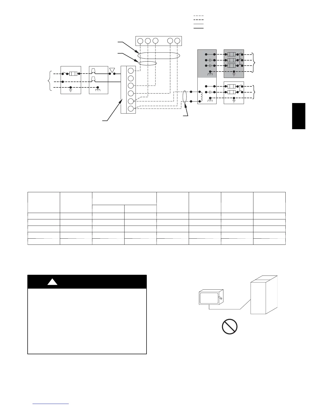
Details electrical connection requirements, voltage compatibility, and wiring diagrams.

Combustion Air and Vent Pipe Systems

Explains direct vent and ventilated combustion air system options and their requirements.

Vent and Combustion Air Pipe Sizing and Installation

Provides guidelines for sizing, installing, and insulating combustion air and vent pipes.

Vent Termination Clearances

Specifies required clearances for vent terminals above grade, windows, soffits, and other structures.

Condensate Drain System

Details the installation and protection of the condensate drain system, including trap priming.

Start-Up, Adjustments, and Safety Check

Initial Start-Up and General Checks

Outlines initial checks for power, grounding, thermostat wiring, and blower door installation.

Setup Switch Configuration

Explains how to configure setup switches for A/C, CF, and other operational modes.

Priming the Condensate Trap

Describes the process of priming the condensate trap to ensure proper draining.

Gas Input Rate and Manifold Pressure Adjustment

Details how to set gas input rate and manifold pressure according to altitude and gas properties.

Temperature Rise Measurement

Explains how to measure and ensure the air temperature rise is within specified limits.

Safety Control Checks

Covers verification of the primary limit control and pressure switches for safe operation.

Installation Checklist

Provides a comprehensive checklist to ensure all installation steps are completed correctly.

Related product manuals