17
L
E
G
E
N
D
JUNCTION
TERMINAL
CONTROL TERMINAL
FACTORY POWER
WIRING (115VAC)
FACTORY CONTROL
WIRING (24VAC)
FIELD CONTROL
WIRING (24VAC)
CONDUCTOR ON
CONTROL
FIELD WIRING
SCREW TERMINAL
EQUIPMENT
GROUND
PLUG RECEPTACLE
NOTES:
332710-101 REV. A
1. If any of the original equipment wire is replaced use wire rated for 105°C.
2. Use only copper wire between the disconnect switch and the furnace junction box (JB).
3. This wire must be connected to furnace sheet metal for control to prove flame.
4. Symbols are electrical representation only.
5. Solid lines inside PCB are printed circuit board conductors and are not included in legend.
6. Replace only with a 3 amp fuse.
7. Inductor is used with 3/4 hp and 1 hp ECM Blower motors.
8. Factory connected when (LGPS) not used.
9. Blower off-delay, gas heating selections are (90, 120, 150, 180) seconds, cooling or heat pump
90 seconds or 5 seconds when dehumidify call is active.
10. Ignition lockout will occur after four consecutive unsuccessful trials for ignition. Control will
auto-reset after three hours.
11. Any of the 5 wires shown within the NEUTRAL L2 box can be connected to any terminal within the box.
12. Blower motor (BLWM) and Inducer motor (IDM) are locked-rotor overload protected by redundant
electronic control circuits.
A/C Air Conditioning (Adjustable Airflow -CFM)
ACR Air Conditioning Relay, SPST (N.O.)
ACRDJ Air Conditioning Relay Defeat Jumper
BLWM Blower Motor (ECM)
CF Continuous Fan (Adjustable Airflow -CFM)
COMMR Communication Relay, SPDT
CPU Microprocessor / Circuitry
DHUM DHUM Connection (24VAC )
EAC-1 Electronic Air Cleaner Connection
(115VAC 1.0 Amp Max.)
EAC-2 Electronic Air Cleaner Connection (Common)
FRS Flame Rollout Switch, Man. Reset, SPST(N.C.)
FSE Flame-Proving Sensor Electrode
FUSE Fuse, 3 Amp, Automotive Blade Type,
Factory Installed
GV Gas Valve
GVR Gas Valve Relay, DPST (N.O.)
HPS High-Heat Pressure Switch, SPST (N.O.)
HPSR High-Heat Pressure Switch Relay, SPST (N.C.)
HSI Hot Surface Igniter (115VAC)
HSIR Hot Surface Igniter Relay, SPST (N.O.)
HUM 24VAC Humidifier Connection (0.5 Amp Max.)
HUMR Humidifier Relay, SPST (N.O.)
IDM Inducer Draft Motor, 2-Speed, Shaded Pole
IDR Inducer Motor Relay, SPST (N.O.)
IHI/LOR Inducer Motor Speed Change Relay, SPDT
ILK Blower Door Interlock Switch, SPST (N.O.)
IND Inductor (Note #7)
LED Light Emitting Diode for Status Codes
LGPS Low Gas Pressure Switch, SPST (N.O.)
LPS Low-Heat Pressure Switch, SPST (N.O.)
LS Limit Switch, Auto-Reset, SPST (N.C.)
PCB Printed Circuit Board
PL1 12-Circuit Connector
PL2 4-Circuit HSI & IDM Connector
PL3 4-Circuit ECM BLWM Connector
PL4 4-Circuit Model Plug Connector
PL7 4-Circuit Communication Connector
PL9 2-Circuit OAT Connector
PL10 2-Circuit HSI Connector
PL11 IDM Connector (12-Circuit)
PL12 1-Circuit Inductor Splice Connector
PL13 16-Circuit ECM Blower Ctrl. Connector
PL14 5-Circuit ECM Blower Power Connector
SW1-1 Manual Switch, Status Code Recall, SPST (N.O.)
SW1-2 Manual Switch, Low-Heat Only, SPST(N.O.)
SW1-3 Manual Switch, Low-Heat Rise Adj. SPST (N.O.)
SW1-4 Manual Switch, Comfort/Efficiency Adjustment,
SPST (N.O.)
SW1-5 Manual Switch, Cooling CFM/Ton, SPST (N.O.)
SW1-6 Manual Switch, Component Test, SPST (N.O.)
SW1-7,8 Manual Switches, Blower Off-Delay, SPST(N.O.)
SW4-1 Manual Switch, Twinning Main (OFF) / Sec. (ON)
SW4-2&3 FOR FUTURE USE
TRAN Transformer, 115VAC / 24VAC
GV
M
C
HI
NOTE #3
BLU
BRN
HPS
GRN/YEL
FRS
LS
NOTE #8
GRY
RED
RED RED
LPS
(WHEN USED)
LGPS
BRN
FSE
WHT
PL3
1
4
HSI
L1
FUSED OR CIRCUIT
BREAKER DISCONNECT
SWITCH (WHEN REQ'D)
NOTE #2
GND
NEUTRAL
FU2
BLK
ILK
PL10
JB
1
2
BLK
WHT
PL1
TRAN
BLWM
L1
EAC-1
PL12
IND
NOTE #7
PL12
4
HSI
PL2
VS
BLK
WHT
WHT
BLU
SEC-2
CODE
SEC-1
HUM
FUSE 3-AMP
W/W1DHUM G
24V
om
C
W2 Y/ Y2 RY1
STATUS
LEDS
COMM
ACRDJ
PL8
PL9
OAT
SW4
PL7
ABCD
CF
AC
SW1
PL4
GRN/YEL
1. Default A/C airflow when A/C switches are in OFF position
2. Default cont. fan airflow when CF switches are in OFF position
A/C OR CF AIRFLOW SELECTION CHART BASED ON 350 CFM/TON
1
HSI
2
SCHEMATIC DIAGRAM
IDR
TO 115VAC FIELD-DISCONNECT SWITCH
ILK
EQUIPMENT
GROUND
1
2
3
HSIR
IHI/LOR
PL2
L2
L2
FU1
NOTE #6
PL1-8
R
PL1-6
L2
PL10
4
CPU
NOTE #5
PCB
PL3
123 4
BLWM
PL13
10
16
1
7
5
4
3
2
1
EAC-1
PL14
PL12
IND
NOTE #7
PL12
L1
EAC
EAC-2
TRAN
115VAC
L1
L2
SEC2
SEC1
24VAC
PL1-12
HPSR
GV
LPS
NOTE #8
LGPS
(WHEN USED)
HPS
HI
PL1-2
PL1-4
PL1-3
PL1-10
PL1-5
W/W1
CPU
GVR
DHUM
W2
Y/Y2
G
Y1
COM
NOTE #3
C
M
PL1-1
FSE
NOTE #5
ACR
COMMR
PCB
1
1
1
2
210017501400
122512251225
1225
1050
1050
875
875
700
700
525
120
5T080,100
DEF.
DEF.
DEF.
060
3.5T080
SIZE
MODEL
1 2 3
OFF
1 2 3
OFF
1 2 3
OFF
1 2 3
OFF
1 2 3
OFF
1 2 3
OFF
1 2 3
OFF
1 2 3
OFF
ORN
BLK
GRN/YEL
5
16
17
10
BLU
YEL
GRN
RED
PL13
PL14
BLK
YEL
CONNECTION DIAGRAM
BLK
WHT
YEL
1
4
3
2
BLU
YEL
GRN
RED
SW1-7,8
BLOWER OFF DELAY
SELECTION
90
SEC
120
SEC
150
SEC
180
SEC
OFF
OFF OFF
OFF
7 8 7 8 7 8
7 8
1
1
2
1
1
ACRDJ
PRINTED CIRCIUT BOARD
PRINTED CIRCIUT BOARD
HUMR
HUM
RED
MODEL
MODEL
SIZE
PLUG
HK70EZ
PIN RESISTANCE K
1 - 4
2 - 3
060
3.5T080
5T-080
100
057
058
059
060
24
24
24
24
91
120
150
180
PL4 - MODEL PLUG CHART
120 061
24
220
2
700
875 1050 1225 1400
1
1750
1750
IDM
GRN/YEL
BRN
ORN
YEL
WHT
BLK
BLK
WHT
FRS
LS
IDM
PL11
PL1-9
PL1-11
PL1-7
L2
NOTE #11
NEUTRAL - L2
EAC-2
WHT
RED
4
2
10
1
12
6
4
2
10
1
12
6
* * * * * * * * * * * * * * * * * * * * * * * * * * * * * * * * * * * * * * * * * * ** * * * * * * * * * * * * * * * * ** * * * * * * * * * * * * * * * *
* * * * * * * * * * * * * * * * * * * * * * * * * * * * * * * * * * * * * * * * * * ** * * * * * * * * * * * * * * * * ** * * * * * * * * * * * * * * * *
* * * * * * ** * * * * * * * * * * * * * * * * * * * * * * ** * * * * * * * * * * * * * * * * * * * * * * * * * * * * * *
* * * * * * ** * * * * * * * * * * * * * * * * * * * * * * ** * * * * * * * * * * * * * * * * * * * * * * * * * * * * * *
* * * * * * * * * * * * * * * * * * * * * * * * * * * * * * * * * * * * * * * * * * ** * * * * * * * * * * * * * * * * ** * * * * * * * * * * * * * *
* * * * * * * * * * * * * * * * * * * * * * * * * * * * * * * * * * * * * * * * * * ** * * * * * * * * * * * * * * * * ** * * * * * * * * * * * * * *
*
* * * * * * ** * * * * * * * * * * * * * * * * * * * * * * ** * * * * * * * * * * * * * * * * * * * * * * * * * * * * *
* * * * * * ** * * * * * * * * * * * * * * * * * * * * * * ** * * * * * * * * * * * * * * * * * * * * * * * * * * * * *
*
A06459
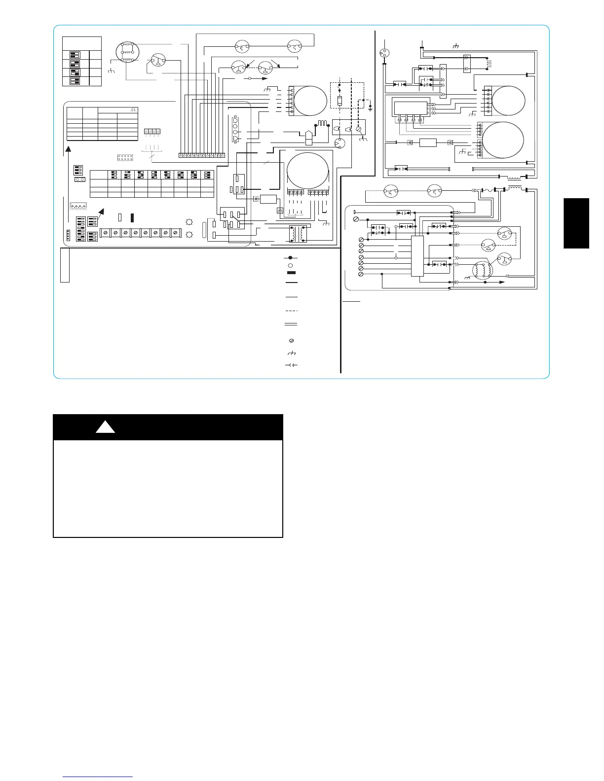
Fig. 23 --- Wiring Diagram
UNIT DAMAGE HAZARD
Failure to follow this caution may result in unit component
damage.
DO NOT connect furnace control HUM terminal to HUM
(humidifier) terminal on Thermidistatt, Zone Controller or
similar device. See Thermidistatt, Zone Controller,
thermostat, or controller manufacturer’s instructions for
proper connection.
CAUTION
!
2. Humidifier (HUM)
Connect an accessory 24 VAC, 0.5 amp maximum
humidifier (if used) to the 1/4-- in. male quick--connect
HUM terminal and COM-- 24V screw terminal on the
control board thermostat strip. The HUM terminal is
energized when blower is energized in heating. (See Fig.
23 and 33.)
Step 8 —Removal of Existing Furnaces from
Common Vent Systems
When an existing Category I furnace is removed or replaced, the
original venting system may no longer be sized to properly vent
the remaining attached appliances. An improperly sized Category
I venting system could cause the formation of condensate in the
furnace and vent, leakage of condensate and combustion
products, spillage of combustion products into the living space,
etc.
58UVB