34
AIR CONDITIONING AIRFLOW* 060 & 080-14
MODEL
080-20 & 100
MODEL
120 MODEL
TONS (12,000 BTU/HR) (CFM)
1-1/2 525 (600) X
X
2 700 (800) X X X
2-1/2 875 (1000) X X X
3 1050 (1200) X X X
3-1/2 1225 (1400) X X X
4 1400 (1600) X X
5 1750 (2000) X
6 2100 (2100) X
X-INDICATES AN ALLOWABLE SELECTION.
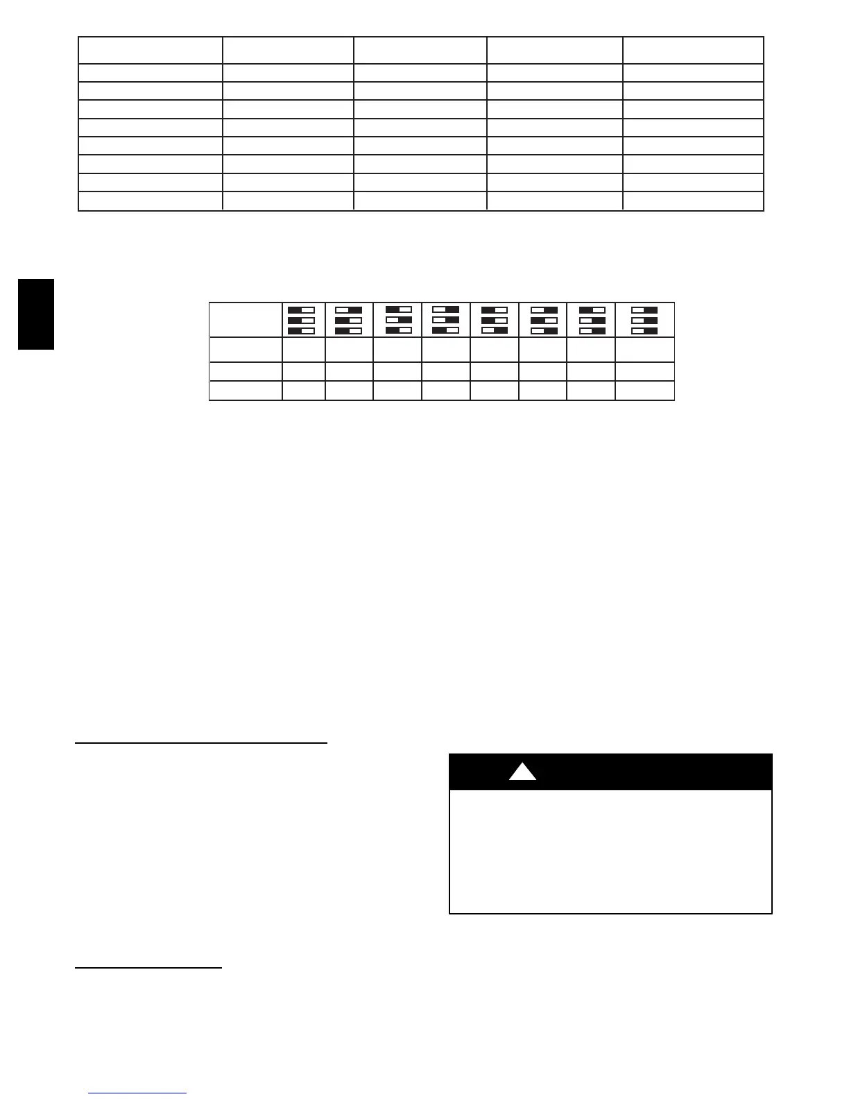
A/C OR CF AIRFLOW SELECTION CHART
BASED ON 350 CFM/TON
MODEL
SIZE
060,
080-14
DEF 525
2
700 875 1050
1
1225 1225 1225
080-20, 100 DEF 700 875 1050 1225 1400 1750
1
1750
120 DEF 700 875
2
1050 1225 1400 1750
1
2100
1.DEFAULT A/C AIRFLOW WHEN A/C SWITCHES ARE IN OFF POSITION
2.DEFAULT CONT. FAN AIRFLOW WHEN CF SWITCHES ARE IN OFF POSITION
2
* Airflow shown in parentheses is airflow unit that the unit will deliver when setup switch SW1-5 is ON (selects 400 CFM/ton)
A06508
Fig. 39 --- A/C or CF Airflow Selection Chart Based on 350 and 400CFM/Ton
3. Determine air conditioning tonnage used.
4. Use wiring schematic to determine proper setup position
of A/C switches. (See Fig. 23 and 39.)
NOTE: Excessive airflow caused by improper A/C switch setup
may cause condensate blowoff in cooling mode.
5. Replace main furnace door and blower access panel.
NOTE: EAC--1 terminal is energized whenever blower operates.
HUM terminal is only energized when blower is ener gized in
heating.
CONTINUOUS FAN (CF) SETUP
SWITCHES
The CF setup switches are used to select desired airflow when
thermostat is in continuous fan mode or to select low-- cooling
airflow for two --speed cooling units. This setup feature allows
continuous fan airflow or low--cooling airflow to be adjusted. To
set desired continuous fan airflow or low--cooling airflow:
1. Remove main furnace door and blower access panel.
2. Locate CF setup switches on furnace control. (See Fig.
33.)
3. Determine desired continuous fan airflow or low--cooling
airflow.
4. Use wiring schematic to determine proper setup position
of CF switches. (See Fig. 23 and 39.)
5. Replace main furnace door and blower access panel.
SETUP SWITCHES
(SW1)
The furnace control has 8 setup switches that may be set to meet
the application requirements. Position these setup switches for the
appropriate requirement.
1. Remove main furnace door and blower access panel.
2. Locate setup switches on furnace control. (See Fig. 33.)
3. See Table 9 for setup switch description. (See Fig. 23.))
4. Replace main furnace door and blower access panel.
NOTE: If a bypass humidifier is used, setup switch SW1 -- 3
(Low HEAT Rise Adjust) should be in ON position. This
compensates for the increased temperature in return air resulting
from bypass.
NOTE: If modulating dampers are used, blower motor
automatically compensates for modulating dampers.
Step 3 —Prime Condensate Trap With Water
UNIT MAY NOT OPERATE
Failure to follow this caution may result in intermittent unit
operation or performance satisfaction.
Condensate trap must be PRIMED or proper draining may
not occur. The condensate trap has 2 internal chambers
which can ONLY be primed by pouring water into the
inducer drain side of condensate trap.
CAUTION
!
1. Remove upper inducer housing drain connection cap. (See
Fig. 41.)
2. Connect field-- supplied 1/2--in. ID tube to upper inducer
housing drain connection.
3. Insert field-- supplied funnel into tube.
4. Pour 1 quart of water into funnel/tube. Water should run
through inducer housing, overfill condensate trap, and
flow into open field drain. (See Fig. 42.)
58UVB
 Loading...