T -304
5--6
04/08
5.12 SERVICING THE HEAT VALVE
The heat valve (Figure 5--6) requires no maintenance
unless a malfunction to the internal parts or coil occurs.
This may be caused by foreign material such as: dirt,
scale, or sludge in the coolant system, or improper
voltage to the coil.
NOTE
TheOEMsuppliedheating(hot water)Solenoid
Valve is normally located outside of the
AC310/350 rooftop air conditioning system.
There are only three possible valve malfunctions: coil
burnout, failure to open, or failure to close.
Coil burnout may be caused by the following:
1. Improper voltage
2. Continuous over-voltage, more than 10% or Under-
voltage of more than 15%.
3. Incompletemagneticcircuitduetotheomissionofthe
coil housing or plunger.
4. Mechanical interference with movement of plunger
which may be caused by a deformed enclosing tube.
Failure to open may be caused by the following:
1.Coil burned out or an open circuit to coil connections.
2. Improper voltage.
3. Torn diaphragm.
4. Defective plunger or deformed valve body assembly.
Failure to close may be caused by the following:
1. Defectiveplungerordeformedvalvebodyassembly.
2. Foreign material in the valve.
3. Torn diaphragm.
2.
3.
4.
5.
6.
7.
8.
9.
10.
1.
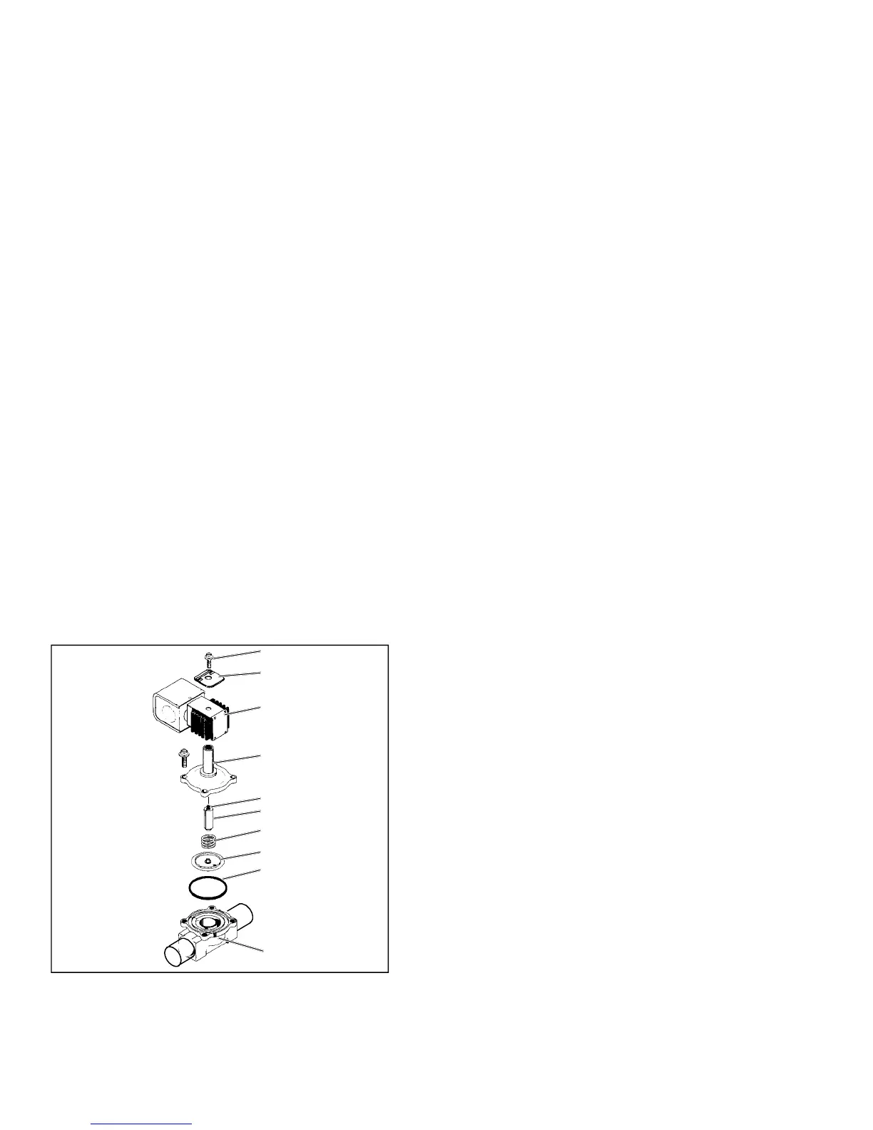
Figure 5--6 Heat Valve
1. Coil Retaining Screw
2. Nameplate
3. Coil Housing
Assembly
4. Enclosing Tube &
Bonnet Assembly
5. Kick-O
Spring
6. Plunger
7. Closing Spring
8. Diaphragm
9. O-Ring
10. Valve Body
5.12.1 Coil Replacement
a. It is not necessary to drain the coolant from the sys-
tem.
b. Placemainbatterydisconnect switchin OFF position
and lock.
c. Disconnect wire leads to coil.
d. Remove coil retaining screw and nameplate.
e. Lift burned-out coil from enclosing tube and replace.
f. Connect wire leads and test operation.
5.12.2 Internal Part Replacement
a. Disconnect system from bus battery.
b. Open the vent fitting at the top of the outlet header of
the heater coil.
c. Drain coil by opening the drain-cock on the inlet tube.
d. Disassemble valve and replace defective parts.
e. Assemble valve, refill and bleed coolant lines.
5.12.3 Replace Entire Valve
a. Disconnect system from bus battery.
b. Drain coolant from lines as previously described and
disconnect hoses to valve .
c. Disconnect wire leads to coil.
d. Remove valve assembly from bracket.
e. Install new valve and re-connect hoses. It is not ne-
cessaryt odisassemblethevalvewheninstalling.
f. Refill and bleed coolant lines.
g. Connect wire leads and test operation.
5.13 SERVICING THE LIQUID LINE SOLENOID
VALVE
The Liquid line solenoid valve (Figure 5--7) is very
similar to the heat valve. It requires no maintenance
unless a malfunction to the internal parts or coil occurs.
This may be caused by foreign material such as: dirt,
scale, or sludge in the refrigeration system, or improper
voltage to the coil.
There are only three possible valve malfunctions: coil
burnout, failure to open, or failure to close.
Coil burnout may be caused by the following:
1. Improper voltage.
2. Continuous over-voltage, more than 10% or under-
voltage of more than 15%.
3. Incomplete magnet circuit due to the omission of the
coil hosing or plunger.
4. Mechanical interface with movement of plunger
which may be caused by a deformed enclosing tube.
 Loading...