Manufacturer reserves the right to discontinue, or change at any time, specifications or designs without notice and without incurring obligations.
Catalog No. 04-53300221-01 Printed in U.S.A. Form 30RAP-7T Rev. A Pg 1 5-21 Replaces: 30RAP-6T
Controls, Start-Up, Operation,
Service, and Troubleshooting
CONTENTS
Page
SAFETY CONSIDERATIONS . . . . . . . . . . . . . . . . . . . 2
GENERAL . . . . . . . . . . . . . . . . . . . . . . . . . . . . . . . . . . . 3
Conventions Used in This Manual . . . . . . . . . . . . . . . 3
Basic Controls Usage . . . . . . . . . . . . . . . . . . . . . . . . . 4
• SCROLLING MARQUEE DISPLAY
• ACCESSORY NAVIGATOR™ DISPLAY MODULE
CONTROLS . . . . . . . . . . . . . . . . . . . . . . . .
. . . . . . . . . 7
General . . . . . . . . . . . . . . . . . . . . . . . . . . . . . . . . . . . . . 7
Main Base Board (MBB) . . . . . . . . . . . . . . . . . . . . . . 26
Energy Management Module (EMM) . . . . . . . . . . . . 27
Current Sensor Board (CSB) . . . . . . . . . . . . . . . . . . 27
Auxiliary (AUX) Board . . . . . . . . . . . . . . . . . . . . . . . . 27
Electronic Expansion Valve (EXV) Board
. . . . . . . . 27
Compressor Expansion Board (CXB) . . . . . . . . . . . 27
Enable/Off/Remote Control Switch . . . . . . . . . . . . . 27
Emergency On/Off Switch . . . . . . . . . . . . . . . . . . . . 27
Board Addresses . . . . . . . . . . . . . . . . . . . . . . . . . . . 27
Control Module Communication . . . . . . . . . . . . . . . 27
• RED LED
• GREEN LED
• YELLOW LED
Carrier Comfort Network
®
(CCN) Interface . . . . . . . 28
Alarm
Control . . . . . . . . . . . . . . . . . . . . . . . . . . . . . . 29
• ALARM ROUTING CONTROL
• ALARM EQUIPMENT PRIORITY
• COMMUNICATION FAILURE RETRY TIME
• RE-ALARM TIME
• ALARM SYSTEM NAME
Sensors . . . . . . . . . . . . . . . . . . . . . . . . . . . . . . . . . . . 29
• COOLER LEAVING FLUID SENSOR
• COOLER ENTERING FLUID SENSOR
• COMPRESSOR RETURN GAS TEMPERATURE
SENSOR
• OUTDOOR-AIR TEMPERATURE SENSOR (OAT)
• DISCHARGE TEMPERATURE THERMISTOR (DTT)
• REMOTE SPACE TEMPERATURE SENSOR OR DUAL
LEAVING WATER TEMPERATURE SENSOR
Energy Management Module . . . . . . . . . . . . . . . . . . 30
Loss-of-Cooler Flow Protection . . . . . . . . . . . . . . . . 31
Electronic Expansion Valves (EXVs) . . . . . . . . . . . . 31
Capacity Control . . . . . . . . . . .
. . . . . . . . . . . . . . . . . 31
• MINUTES LEFT FOR START
• MINUTES OFF TIME
• LEAD/LAG DETERMINATION
• LOADING SEQUENCE SELECT
• LOW AMBIENT LOCKOUT
• CAPACITY CONTROL OVERRIDES
• SLOW CHANGE OVERRIDE
Head Pressure Control . . . . . . . . . . . . . . . . . . . . . . .34
• MOTORMASTER
®
V OPTION
High-Efficiency Variable Condenser Fans . . . . . . . .37
• 30RAP011-060 WITH GREENSPEED
®
INTELLIGENCE
• FAN DRIVE OPERATION
Operation of Machine Based on Control Method and
Cooling Set Point Selection Settings . . . . . . . . .38
• OCCUPANCY SCHEDULE
• CCN CONTROL
Cooling Set Point Select . . . . . . . . . . . . . . . . . . . . . .39
• SINGLE
• DUAL SWITCH
• DUAL CCN OCCUPIED
• 4 TO 20 MA INPUT
• CONFIGURATION SET POINT LIMITS
Ice Mode . . . . . . . .
. . . . . . . . . . . . . . . . . . . . . . . . . . .39
Cooling Set Point (4 to 20 mA) . . . . . . . . . . . . . . . . .39
Low Sound Mode Operation . . . . . . . . . . . . . . . . . . .40
Heating Operation . . . . . . . . . . . . . . . . . . . . . . . . . . .40
Service Test . . . . . . . . . . . . . . . . . . . . . . . . . . . . . . . .40
Optional Factory-Installed Hydronic Package . . . .41
Cooler
Pump Control . . . . . . . . . . . . . . . . . . . . . . . . .41
Cooler Pump Operation . . . . . . . . . . . . . . . . . . . . . . .41
Cooler Pump Sequence of Operation . . . . . . . . . . .41
• NO INTEGRAL PUMP — SINGLE EXTERNAL PUMP
CONTROL
• NO INTEGRAL PUMP — DUAL EXTERNAL PUMP
CONTROL
• SINGLE INTEGRAL PUMP CONTROL
• DUAL INTEGRAL PUMP CONTROL
Configuring and Operating Dual Chiller Control . .43
Temperature Reset . . . . . . . . . . . . . . . . . . . . . . . . . .43
Demand Limit . . . . . . . . . . . . . . . . . . . . . . . . . . . . . . .
49
• DEMAND LIMIT (2-STAGE SWITCH CONTROLLED)
• EXTERNALLY POWERED DEMAND LIMIT (4 TO 20
MA CONTROLLED)
• DEMAND LIMIT (CCN LOADSHED CONTROLLED)
Digital Scroll Option . . . . . . . . . . . . . . . . . . . . . . . . .49
• DIGITAL SCROLL OPERATION
• DIGITAL COMPRESSOR CONFIGURATION
PRE-START-UP . . . . . . . . . . . . . . . . . . . . . . . . . . . . .51
System Check . . . . . . . . . . . . . . . . . . . . . . . . . . . . . .51
START-UP AND OPERATION . . . . . . . . . . . . . . . . . .51
Crankcase Heaters . . . . . . . . . . . . . . . . . . . . . . . . . . .52
Actual Start-Up . . . . . . . .
. . . . . . . . . . . . . . . . . . . . . .52
Check Refrigerant Charge . . . . . . . . . . . . . . . . . . . . .52
Charge Adjustment for Brine Operation . . . . . . . . .52
Operating Limitations . . . . . . . . . . . . . . . . . . . . . . . .52
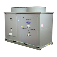
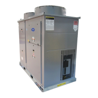
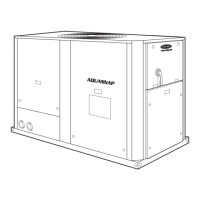
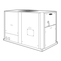
AquaSnap
®
30RAP010-150 Air-Cooled Chillers and
30RAP011-060 Air-Cooled Chillers with
Greenspeed
®
Intelligence
with Puron
®
Refrigerant (R-410A)
50/60 Hz