Do you have a question about the Carrier AquaSnap 30RAN010-055 and is the answer not in the manual?
Warning to open all remote disconnects before servicing the equipment.
Connecting fluid piping and drain lines for units without hydronic packages.
Procedures for unit preparation for year-round operation or winter shutdown.
Explanation of closed water systems and the function of hydronic packages.
Managing air in water loops and connecting water lines to the unit.
Importance and procedures for cleaning water systems to prevent component damage.
Electrical characteristics, field wiring size, and supply voltage for power connections.
Safety warnings, general wiring notes, and control circuit power details.
Guidance on installing optional electrical accessories and low-ambient controls.
Information on minimum load and other miscellaneous accessories for the unit.
Wiring diagrams for standard and non-fused disconnect power and control connections.
Wiring diagrams for power supply and control connections for 30RA032-055 units.
Procedures for leak testing and dehydrating the refrigerant circuit of the unit.
Guidelines for charging refrigerant and a warning about freezing damage during charging.
Charts showing water pressure drop vs. GPM for units without pumps.
Charts showing water pressure drop vs. GPM for units with single pump units.
Charts showing water pressure drop vs. GPM for units with dual pump units.
Pressure drop curves for accessory storage tanks based on flow rate.
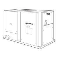
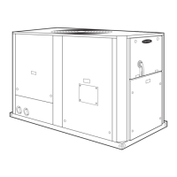
The AquaSnap™ 30RAN010-055 Chiller is a robust and versatile cooling unit designed for various applications, offering efficient performance and ease of maintenance. This chiller is equipped with advanced controls and features to ensure reliable operation and simplified servicing.
The AquaSnap™ chiller's primary function is to provide chilled water for cooling systems. It operates by circulating a refrigerant through a closed circuit, absorbing heat from the water loop, and then releasing that heat to the ambient air. The unit is available in various sizes, with or without hydronic packages, to suit different system requirements. The hydronic package, when included, integrates components such as a pump, expansion tank, and air separator, simplifying installation and ensuring proper water flow and air management within the system.
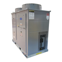
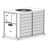
The chiller is designed for outdoor installation and can be used in both primary-secondary and variable primary flow systems. Its control system, Carrier ComfortLink™, allows for precise temperature management and system optimization. The unit can be configured for different operating modes, including cooling, and offers features like demand limit and ice done options for energy management.
The AquaSnap™ chiller is designed for straightforward installation and operation. Before installation, a thorough site survey is required to ensure proper clearances for airflow, service access, and structural support. The unit's rigging and placement are critical, requiring careful consideration of weight distribution and lifting points to prevent damage.
Electrical connections are made through a dedicated disconnect switch, and the unit supports various voltage configurations. Field power supply knockouts are provided for convenience. For units with hydronic packages, water connections are made using copper or brass FPT fittings, and it's crucial to avoid dissimilar metals to prevent galvanic corrosion. The system requires proper water treatment and cleaning to prevent fouling and damage to internal components. A side stream filter is recommended during the cleaning process to remove particulates.
The chiller's control panel, accessible through a service door, allows operators to monitor system status, adjust settings, and troubleshoot issues. The ComfortLink™ controls provide a user-friendly interface with diagnostic capabilities, including alarm codes and operating modes. Remote on-off control and other accessory connections are available for integration into building management systems.
For optimal performance, the water loop must be properly filled and air-separated. Automatic air vents should be installed at high points in the system, and an air separator is recommended at the point of highest water temperature and lowest pressure, typically in the chilled water return piping. This ensures efficient heat transfer and prevents issues like noise, reduced terminal output, and pump cavitation.
The chiller is equipped with a strainer and a blow-down valve, allowing for the removal of particulates without fully disassembling the unit. The ComfortLink™ controls can be configured to remind operators to clean the strainer at preset intervals, further simplifying routine maintenance.
The AquaSnap™ chiller is designed with maintenance in mind, incorporating features that facilitate servicing and extend the unit's lifespan. Regular leak testing of the refrigerant circuit is essential, especially after installation, to ensure system integrity. The unit is shipped with a full charge of R-22 refrigerant, and service valves with Schrader connections are provided for charging and pressure measurement.
When charging the refrigerant, it is crucial to circulate water through the cooler at all times to prevent freezing, which can cause severe damage and void the warranty. Overcharging should also be avoided, as it can lead to higher discharge pressures, increased cooling fluid consumption, compressor damage, and higher power consumption.
The compressors are equipped with 1/4-in. Schrader fittings for connecting to low-side system pressure gauges, allowing technicians to easily monitor refrigerant levels. If the unit includes a Motormaster® V control, the pressure transducer must be removed from the liquid line Schrader connection to access the gauge.
The control system provides diagnostic information, including alarm codes, which help in quickly identifying and addressing operational issues. The ability to access various operating modes and settings through the control panel simplifies troubleshooting and performance optimization.
For units with hydronic packages, the strainer with a blow-down valve allows for easy removal of particulates, reducing the need for full system drainage during routine cleaning. The ComfortLink™ controls can be programmed to prompt for strainer cleaning, ensuring that this critical maintenance task is not overlooked.
Overall, the AquaSnap™ 30RAN010-055 Chiller is a reliable and efficient cooling solution, offering a blend of advanced technology, user-friendly features, and simplified maintenance procedures to ensure long-term performance and operational efficiency.
| Model | 30RAN010-055 |
|---|---|
| Category | Chiller |
| Compressor Type | Scroll |
| Refrigerant | R-410A |
| Power Supply | 208-230/460V, 3-phase, 60 Hz |
| Control System | Microprocessor-based |
| Operating Range (Ambient Temp) | -20°F to 125°F |
| Cooling Capacity (Tons) | 10-55 tons |